Central locking
Assembly overview - Central locking
Assembly overview - Central locking
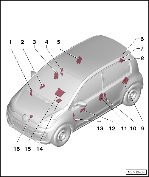
- Coupling station
- Installation location: A-pillar, right
- To disconnect the plug connector, release the bellows on the pillar.
- Door control module, passenger side -J387-
- integrated in window regulator motor, passenger side -V148-
- Remove and install
- Door lock, passenger side
- The door lock is attached to the inner door panel.
- The electric central locking is integrated in the door lock.
- Remove and install
- Coupling station
- Installation location: B-pillar, right
- To disconnect the plug connector, release the bellows on the pillar.
- Door lock, rear right
- The door lock is attached to the inner door panel.
- The electric central locking is integrated in the door lock.
- Remove and install
- Button for unlocking in tailgate handle -E234-
- Installation location: on the tailgate
- Remove and install
- Coupling station
- Installation location: C-pillar, upper left
- To disconnect the plug connector, remove the C-pillar trim.
- Tailgate lock
- Installation location: on the tailgate
- Remove and install
- Door lock, rear left
- The door lock is attached to the inner door panel.
- The electric central locking is integrated in the door lock.
- Remove and install
- Coupling station
- Installation location: B-pillar, left
- To disconnect the plug connector, release the bellows on the pillar.
- Door lock, driver side
- The door lock is attached to the inner door panel.
- The electric central locking is integrated in the door lock.
- Remove and install
- Door control module, driver side -J386-
- integrated in window regulator motor, driver side -V147-
- Remove and install
- Coupling station
- Installation location: A-pillar, left
- To disconnect the plug connector, release the bellows on the pillar.
- Alarm horn -H12-
- optional
- Installation location: in the cowl
- Remove and install
- Onboard power supply control module -J519-
- Installation location: under the dash panel, driver side, clipped onto the relay carrier
- removing and installing → Electrical system
- Contact switch for hood -F266-
- Installation location: on hood latch
- removing and installing → Electrical system
Assembly overview - Battery for ignition key
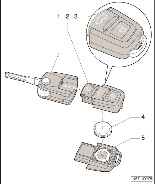
- Key with rolling code transponder
- Radio container - upper part
- Light-emitting diode
- This light-emitting diode must flash when the remote control is operated.
- If the LED does not flash when the remote control is pressed, the battery is flat and must be replaced.
- Battery
- Remove and install
- Radio container - lower section
Removing and installing the battery for the ignition key
Removing
Carry out the following work:
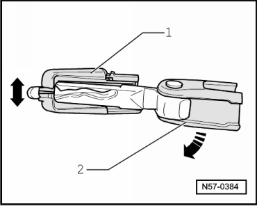
- Insert a screwdriver into the slot between the radio container -1- and the key -2-.
- Turn the screwdriver in the direction of the arrow to separate the radio container from the key.
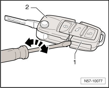
- Press the radio container -1- apart from the key blade of the key -2-.
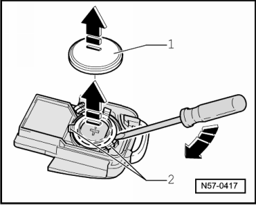
- Using a screwdriver, unclip the battery -1- from the holders -2- by moving it in the direction of the arrow.
Installing

Note
- Be sure to press any button once before installing the battery.
- This resets the radio container to its initial state, so that it can only now recognize a new battery.
Carry out the following work:
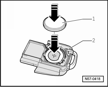
When installing the battery, observe the polarity and installation position.
- Place the battery -1- into the radio container -2- with the positive terminal facing down (the positive terminal is marked on the housing).
- Lock the battery into the radio container by applying light pressure in the direction of the arrow.
- Join the cover and the radio container (do not damage the seal).
- Then lock the radio container to the key.
Adapting ignition keys
Keys are adapted using the → vehicle diagnostic tester.
- In the vehicle diagnostic tester, select "Guided Fault Finding".
- Using the Jump button, select "Function/Component Selection".