On-Board Diagnostic System Description
On-Board Diagnostic System Description
(If your vehicle is equipped with OBD II, the label under the hood must read "OBD II compliant" and a 16-pin connector must be present. As a rule, OBD II is fitted to North American models from the 1996 model year and European models from the 2000 model year.)
The OBD system consists of several diagnostic devices that monitor individual parameters of the emission control systems and store detected faults in the memory of the on-board processor as individual trouble codes. The system also checks sensors and actuators, monitors vehicle service cycles, records even intermittent faults that occur during operation, and allows the memory to be cleared.
The models described in this Manual are equipped with an on-board diagnostic system. The main element of the system is the on-board processor, more commonly called the Electronic Control Module (ECM) or the Powertrain Control Module (PCM). The PCM is the brain of the engine management system. Input data is received by the module from various information sensors and other electronic components (switches, relays, etc.). Based on the analysis of data received from the sensors and in accordance with the base parameters stored in the processor memory, the PCM issues commands to activate various control relays and actuators, thereby adjusting the engine operating parameters and ensuring maximum engine output efficiency with minimum fuel consumption. Processor memory data is read using a special scan tool connected to the 16-pin Data Link Connector (DLC) located in the center console, or to the 20-pin diagnostic connector located on the left side of the engine compartment.
* In principle, trouble codes stored in the self-diagnostic system memory can be read using the "Check Engine" lamp.
Special extended warranty coverage applies to the engine control / exhaust emission control components. Do not attempt to diagnose PCM faults or replace system components on your own before the warranty period expires; contact an authorized dealer service center.
Reading Trouble Codes
DME (SAE J1979) codes are transmitted as an 8-bit binary word (byte). Each bit reflects the result of testing a specific electrical circuit of the control system and takes the value 0 if the test passed, and 1 if a fault is detected.
Example of an information byte and the values of its bits
| 1 | 0 | 1 | 1 | 0 | 1 | 1 | 0 |
| 8 | 7 | 6 | 5 | 4 | 3 | 2 | 1 |

Information content of the 5-character SAE code
For a code of the form P 0 3 8 0, read left to right:
Character 1
- P Powertrain
- B Body
- C Chassis
Character 2 Code source
- 0 SAE standard
- 1 BMW-specific
Character 3 System
- 0 Whole system
- 1 Air/fuel induction
- 2 Fuel injection
- 3 Ignition system or misfire
- 4 Auxiliary emission control
- 5 Vehicle speed and idle control
- 6 Control module input and output signals
- 7 Transmission
Characters 4 and 5 Sequential number of the component or circuit fault (00-99)

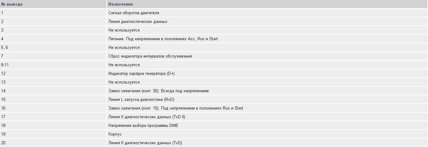
Black, 20-pin diagnostic connector X6002 is located under the hood on the left side of the engine compartment (arrow)
20-pin diagnostic connector pin assignments
Reading Trouble Codes
When a fault recurs in two consecutive trips, the PCM commands the "Check Engine" warning lamp built into the instrument cluster to illuminate; this lamp is also called the malfunction indicator lamp. The lamp will remain on until the self-diagnostic memory is cleared of the stored trouble codes. Trouble codes in the OBD system can be read using the tools described above connected to the diagnostic connector. Other methods are not available on all models. Flashing codes can be read from the "Check Engine" lamp.
Test yourself
A quick BMW 1 quiz: every answer comes with an explanation and a link to the manual page.