Disconnect battery ground cable. To avoid Body Control Module (BCM) damage, it is critical to disconnect battery prior to removal of instrument panel assembly from vehicle. Failure to disconnect battery prior to instrument panel removal will result in BCM being supplied power while losing ground, resulting in internal BCM failure.
Remove heater hoses from heater core.
Remove air conditioning lines from thermal expansion valve.
Remove nuts securing heating control module to module plate.
Remove front floor console as outlined under "Floor Console."
Remove hood latch release handle screws.
Release handle by pulling down cable and unhooking from handle.
Remove hood latch release handle.
Remove driver knee bolster screw.
Release knee bolster from retainer clips.
Remove knee bolster assembly.
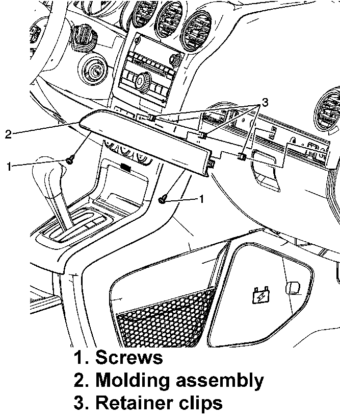
Open instrument panel compartment door to access and remove instrument panel screws, Fig. 1.
Release instrument panel molding assembly from instrument panel retainer clips using a suitable flat-bladed plastic trim tool.
Release instrument panel compartment from four retainer clips.
Remove front floor console storage tray fastener cover and then fastener.
Remove front floor console storage tray assembly.
Starting in lower lefthand corner of upper accessory trim, insert a suitable flat-bladed plastic trim tool between trim plate and edge of console. Pull on upper accessory trim outward as you slide trim tool upward until all clips are disengaged.
Repeat previous step on righthand side of upper accessory trim plate.
Remove front floor console as outlined under "Floor Console."
Disconnect lower accessory trim panel electrical connections.
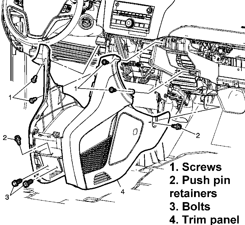
Remove front floor console extension trim panel screws, Fig. 2.
Disconnect range select cable from range select lever.
Disconnect range select lever electrical connector.
Remove automatic transmission range select lever nuts and then automatic transmission range select lever.
Remove transmission control bracket bolts and four transmission control bracket nuts.
Remove transmission control bracket.
Tether clip at upper portion of windshield pillar garnish molding must be replaced every time windshield pillar molding is removed.
Starting at top, gently pull on garnish molding to disengage clip.
Remove lefthand and righthand windshield pillar garnish moldings.
Pull inward at front of carpet retainer to disengage retainer clips from kick panel area, then pull up to disengage remaining retainers. A-Pillar trim and floor carpet retainer are all one piece. Do not attempt to disassemble.
Remove front floor carpet retainers.
Remove brake pedal bracket to tie bar bolt.
Turn steering wheel to straight ahead position.
Insert a small blunt ended punch, or equivalent tool, through access openings on lefthand and righthand side of steering wheel.
Push spring fastener inward to release steering wheel inflator from steering wheel.
Release Connector Position Assurance (CPA) retainer.
Remove steering wheel using puller No. J-1859-A and puller legs No. J-36541-A, or equivalents.
Remove steering column lower trim cover screws.
Steering column lower trim cover may need to be turned slightly to maneuver it around steering column tilt lever.
Remove steering column lower trim cover.
Remove steering column upper trim cover bolts.
Remove steering column upper trim cover. Steering column upper trim cover consists of both cover and instrument panel cluster trim plate bezel. Do not try and separate these pieces; they are serviced as one component only.
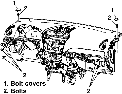
With aid of an assistant, remove instrument panel assembly from vehicle.
Reverse procedure to install, noting following:
a.
Torque instrument panel accessory bezel screws to 27 inch lbs.
b.
Torque instrument panel bolts to 15 ft. lbs.
c.
Torque instrument panel compartment door and compartment door lock screws to 27 inch lbs.
d.
Torque instrument panel inflatable restraint lower bolts to 89 inch lbs.
e.
Torque instrument panel molding screws to 27 inch lbs.
f.
Torque instrument panel retainer nuts to 15 ft. lbs.
g.
Torque instrument panel trim panel bolts to 89 inch lbs.
Fig. 1 Instrument panel molding replacement. Captiva Sport
Fig. 2 Front floor console extension panel replacement. Captiva Sport
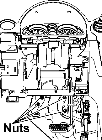
Fig. 3 Instrument panel tie bar to mod plate nuts replacement. Captiva Sport
Fig. 4 Instrument panel replacement. Captiva Sport
Removing the instrument panel in a Chevrolet Captiva 2011 is a meticulous process that requires attention to detail and the use of proper tools. Before starting, it's crucial to disconnect the negative terminal of the battery to prevent any electrical mishaps during the removal. This step ensures safety and prevents damage to sensitive electronic components. As you pull out the instrument panel, disconnect the electrical connections to the instrument cluster, switches, and other controls mounted on the panel. Additionally, detach any air ducts or wiring harnesses connected to the back of the instrument panel. These connections may vary based on the specific model and options in your Captiva.
Once the instrument panel is removed, you'll have access to various components behind the dashboard, such as the instrument cluster, HVAC controls, radio, and potentially the heater core. This accessibility makes it easier to perform maintenance or repairs on these components. When reinstalling the instrument panel, ensure all electrical connections are securely reattached, and the panel is properly aligned before tightening the fasteners and reattaching the trim panels. Finally, reconnect the battery and test the functionality of all controls and gauges to ensure everything is working correctly.
?
Test yourself
A quick Chevrolet Captiva quiz: every answer comes with an explanation and a link to the manual page.