Body and Paint

Diagnosis and Testing - Front Seats

~192min read

Diagnostic Trouble Code (DTC) Chart

The diagnosis in this manual assumes a certain level of skill and knowledge of Ford-approved diagnostic procedures.
REFER TO: Diagnostic Methods (100-00 General Information, Description and Operation).


Diagnostic Trouble Code Chart


Module Trouble Code Description Action
DDM B1C03:23 Memory Switch No. 1: Low Signal GO to Pinpoint Test I
DDM B1C04:23 Memory Switch No. 2: Low Signal GO to Pinpoint Test I
DDM B1C05:23 Memory Switch No. 3: Low Signal GO to Pinpoint Test I
DSM B14C3:24 Rear Seat Height Switch Down: Signal Stuck High GO to Pinpoint Test H
DSM B14C4:24 Rear Seat Height Switch Up: Signal Stuck High GO to Pinpoint Test H
DSM B14CE:09 Horizontal Seat Motor Power: Component Failures GO to Pinpoint Test H
DSM B14CE:11 Horizontal Seat Motor Output: Short to Ground GO to Pinpoint Test H
DSM B14CE:12 Seat Horizontal Motor Output: Short to Battery GO to Pinpoint Test H
DSM B14CE:13 Seat Horizontal Motor Output: Open Circuit GO to Pinpoint Test H
DSM B14CF:11 Seat Tilt Motor Output: Short to Ground GO to Pinpoint Test H
DSM B14CF:12 Seat Tilt Motor Output: Short to Battery GO to Pinpoint Test H
DSM B14CF:13 Seat Tilt Motor Output: Open Circuit GO to Pinpoint Test H
DSM B14D0:11 Front/Tilt Seat Height Motor Output: Short to Ground GO to Pinpoint Test H
DSM B14D0:12 Front/Tilt Seat Height Motor Output: Short to Battery GO to Pinpoint Test H
DSM B14D0:13 Front/Tilt Seat Height Motor Output: Open Circuit GO to Pinpoint Test H
DSM B14D2:11 Rear Seat Height Motor Output: Short to Ground GO to Pinpoint Test H
DSM B14D2:12 Rear Seat Height Motor Output: Short to Battery GO to Pinpoint Test H
DSM B14D2:13 Rear Seat Height Motor Output: Open Circuit GO to Pinpoint Test H
DSM B1B96:24 Seat Slide Forward Switch: Signal Stuck High GO to Pinpoint Test H
DSM B1B97:24 Seat Slide Rearward Switch: Signal Stuck High GO to Pinpoint Test H
DSM B1B98:24 Seat Tilt Up Switch: High Signal Level GO to Pinpoint Test H
DSM B1B99:24 Seat Tilt Switch: High Signal Level GO to Pinpoint Test H
DSM B1C00:24 Seat Tilt Up Switch: Signal Stuck High GO to Pinpoint Test H
DSM B1C01:24 Seat Tilt Switch: High Signal Level GO to Pinpoint Test H
DSM U0100:00 Lost Communication With ECM/PCM "A": No Sub Type Information GO to Pinpoint Test W
DSM U0140:00 Lost Communication With Body Control Module: No Sub Type Information GO to Pinpoint Test K
DSM U0199:00 Lost Communication with Door A Control Module: No Sub Type Information GO to Pinpoint Test AG
DSM U0253:00 Lost Communication with Auxiliary Protocol Interface Module: No Sub Type Information GO to Pinpoint Test AH
DSM U2100:00 Initial Configuration Not Complete: No Sub Type Information GO TO Pinpoint Test AJ
DSM U3000:49 Control Module: Internal Electronic Failure GO to Pinpoint Test AK
DSM U3500:17 Control Module Input Power "A" Circuit Range/Performance: Voltage Above Threshold GO TO Pinpoint Test AI
HVAC B1034:11 Front Left Seat Heater Element: Short to Ground GO TO Pinpoint Test O
HVAC B1034:12 Front Left Seat Heater Element: Short to Battery GO TO Pinpoint Test O
HVAC B1034:13 Front Left Seat Heater Element: Open Circuit GO TO Pinpoint Test O
HVAC B1036:11 Front Right Seat Heater Element: Short to Ground GO to Pinpoint Test P
HVAC B1036:12 Front Right Seat Heater Element: Short to Battery GO to Pinpoint Test P
HVAC B1036:13 Front Right Seat Heater Element: Open Circuit GO to Pinpoint Test P
HVAC B1038:11 Front Left Seat Heater Sensor: Short to Ground GO TO Pinpoint Test O
HVAC B1038:15 Front Left Seat Heater Sensor: Short to Battery or Open Circuit GO TO Pinpoint Test O
HVAC B103A: 11 Front Right Seat Heater Sensor: Short to Ground GO to Pinpoint Test P
HVAC B103A: 15 Front Right Seat Heater Sensor: Short to Battery or Open Circuit GO to Pinpoint Test P
SCME B1151:4B Passenger Seat Cushion: Overheated GO to Pinpoint Test S
SCME B1153:4B Driver Seat Cushion: Overheated GO TO Pinpoint Test R
SCME B1208:11 Driver Seat Cushion Temperature Sensor: Short to Ground GO TO Pinpoint Test R
SCME B1208:15 Driver Seat Cushion Temperature Sensor: Short to Battery or Open Circuit GO TO Pinpoint Test R
SCME B1208:2A Driver Seat Cushion Temperature Sensor: Stuck in Range GO TO Pinpoint Test R
SCME B120A: 11 Passenger Seat Cushion Temperature Sensor: Short to Ground GO to Pinpoint Test S
SCME B120A: 15 Passenger Seat Cushion Temperature Sensor: Short to Battery or Open Circuit GO to Pinpoint Test S
SCME B120A: 2A Passenger Seat Cushion Temperature Sensor: Stuck in Range GO to Pinpoint Test S
SCME B14B9:11 Driver Seat Cushion Thermoelectric Device: Short to Ground GO TO Pinpoint Test R
SCME B14B9:12 Driver Seat Cushion Thermoelectric Device: Short to Battery GO TO Pinpoint Test R
SCME B14B9:13 Driver Seat Cushion Thermoelectric Device: Open Circuit GO TO Pinpoint Test R
SCME B14BB:11 Passenger Seat Cushion Thermoelectric Device: Short to Ground GO to Pinpoint Test S
SCME B14BB:12 Passenger Seat Cushion Thermoelectric Device: Short to Battery GO to Pinpoint Test S
SCME B14BB:13 Passenger Seat Cushion Thermoelectric Device: Open Circuit GO to Pinpoint Test S
SCME B14BD:11 Driver Seat Cushion Fan: Short to Ground GO to Pinpoint Test U
SCME B14BD:13 Driver Seat Cushion Fan: Open Circuit GO to Pinpoint Test U
SCME B14C0:11 Passenger Seat Cushion Fan: Short to Ground GO to Pinpoint Test V
SCME B14C0:13 Passenger Seat Cushion Fan: Open Circuit GO to Pinpoint Test V
SCME B1562:11 Driver Seat Back Fan Speed: Short to Ground GO to Pinpoint Test U
SCME B1562:12 Driver Seat Back Fan Speed: Short to Battery GO to Pinpoint Test U
SCME B1563:11 Passenger Seat Back Fan Speed: Short to Ground GO to Pinpoint Test V
SCME B1563:12 Passenger Seat Back Fan Speed: Short to Battery GO to Pinpoint Test V
SCME B1564:11 Driver Seat Cushion Fan Speed: Short to Ground GO to Pinpoint Test U
SCME B1564:12 Driver Seat Cushion Fan Speed: Short to Battery GO to Pinpoint Test U
SCME B1565:11 Passenger Seat Cushion Fan Speed: Short to Ground GO to Pinpoint Test V
SCME B1565:12 Passenger Seat Cushion Fan Speed: Short to Battery GO to Pinpoint Test V
SCME U0140:00 Lost Communication With Body Control Module: No Sub Type Information GO TO Pinpoint Test X
SCME U0257:00 Communication Lost with Front Controls/Display Interface Module: No Subtype Information GO to Pinpoint Test Y
SCME U1000:00 Solid State Driver Protection Active - Driver Disabled: No Subtype Information GO to Pinpoint Test AL
SCME U2100:00 Initial Configuration Not Complete: No Sub Type Information GO to Pinpoint Test AM
SCME U3000:49 Control Module: Internal Electronic Failure GO to Pinpoint Test AK
SCMG B146F:00 Rear Bladder Electro-Pneumatic Malfunction: No Subtype Information GO to Pinpoint Test L
SCMG B146F:04 Rear Bladder Electro-Pneumatic Failure: Internal System Failures GO to Pinpoint Test L
SCMG B1470:00 Bladder Cushion Electro-Pneumatic Malfunction: No Subtype Information GO to Pinpoint Test L
SCMG B1470:04 Bladder Cushion Electro-Pneumatic System: Internal System Malfunctions GO to Pinpoint Test L
SCMG B1471:11 Multi-Contour Seat Switch Input: Circuit Short to Ground GO to Pinpoint Test L
SCMG B1471:13 Multi-Contour Seat Switch Input: Open Circuit GO to Pinpoint Test L
SCMG B1471:2A Multi-Contour Seat Switch Input: Stuck in Range GO to Pinpoint Test L
SCMG B1473:11 Pump Driver: Short to Ground GO to Pinpoint Test L
SCMG U0140:00 Lost Communication With Body Control Module: No Sub Type Information GO to Pinpoint Test Z
SCMG U0208:00 Communication Lost with Seat Control Module A: No Sub Type Information GO TO Pinpoint Test AA
SCMG U0253:00 Lost Communication with Auxiliary Protocol Interface Module: No Sub Type Information GO to Pinpoint Test AC
SCMG U0256:00 Communication Lost with Front Controls Interface Module "A": No Subtype Information GO to Pinpoint Test advertisement
SCMG U0422:00 Incorrect Data Received from Body Control Module: No Sub Type Information GO TO Pinpoint Test AE
SCMG U0455:00 Incorrect Data Received from Occupant Classification System Module: No Subtype Information GO TO Pinpoint Test AF
SCMG U1000:00 Solid State Driver Protection Active - Driver Disabled: No Subtype Information GO to Pinpoint Test AN
SCMG U2100:00 Initial Configuration Not Complete: No Sub Type Information GO to Pinpoint Test AO
SCMG U3000:49 Control Module: Internal Electronic Failure GO to Pinpoint Test Access Point
SCMG B146F:00 Rear Bladder Electro-Pneumatic Malfunction: No Subtype Information GO to Pinpoint Test M
SCMG B146F:04 Rear Bladder Electro-Pneumatic Failure: Internal System Failures GO to Pinpoint Test M
SCMG B1470:00 Bladder Cushion Electro-Pneumatic Malfunction: No Subtype Information GO to Pinpoint Test M
SCMG B1470:04 Bladder Cushion Electro-Pneumatic System: Internal System Malfunctions GO to Pinpoint Test M
SCMG B1471:11 Multi-Contour Seat Switch Input: Circuit Short to Ground GO to Pinpoint Test M
SCMG B1471:13 Multi-Contour Seat Switch Input: Open Circuit GO to Pinpoint Test M
SCMG B1471:2A Multi-Contour Seat Switch Input: Stuck in Range GO to Pinpoint Test M
SCMG B1473:11 Pump Driver: Short to Ground GO to Pinpoint Test M
SCMG U0140:00 Lost Communication With Body Control Module: No Sub Type Information GO to Pinpoint Test Z
SCMG U0208:00 Communication Lost with Seat Control Module A: No Sub Type Information GO TO Pinpoint Test AA
SCMG U024B:00 Communication Lost with Seat Control Module "G": No Subtype Information GO to Pinpoint Test AB
SCMG U0253:00 Lost Communication with Auxiliary Protocol Interface Module: No Sub Type Information GO to Pinpoint Test AC
SCMG U0256:00 Communication Lost with Front Controls Interface Module "A": No Subtype Information GO to Pinpoint Test advertisement
SCMG U0422:00 Incorrect Data Received from Body Control Module: No Sub Type Information GO TO Pinpoint Test AE
SCMG U0455:00 Incorrect Data Received from Occupant Classification System Module: No Subtype Information GO TO Pinpoint Test AF
SCMG U1000:00 Solid State Driver Protection Active - Driver Disabled: No Subtype Information GO to Pinpoint Test AN
SCMG U2100:00 Initial Configuration Not Complete: No Sub Type Information GO to Pinpoint Test AO
SCMG U3000:49 Control Module: Internal Electronic Failure GO to Pinpoint Test Access Point

Symptom Chart

Symptom Chart: Front Seats

The diagnosis in this manual assumes a certain level of skill and knowledge of Ford-approved diagnostic procedures.
REFER TO: Diagnostic Methods (100-00 General Information, Description and Operation).


Symptom Chart


Condition Possible Sources Action
No Communication with DDM
  • Refer to Pinpoint Test

  • REFER TO: Communication Network (418-00 Communication Network, Diagnosis and Testing).
No Communication with DSM
  • Refer to Pinpoint Test

  • REFER TO: Communication Network (418-00 Communication Network, Diagnosis and Testing).
No Communication with HVAC Module
  • Refer to Pinpoint Test

  • REFER TO: Communication Network (418-00 Communication Network, Diagnosis and Testing).
No Communication with SCME
  • Refer to Pinpoint Test

  • REFER TO: Communication Network (418-00 Communication Network, Diagnosis and Testing).
No Communication with SCMG
  • Refer to Pinpoint Test

  • REFER TO: Communication Network (418-00 Communication Network, Diagnosis and Testing).
No Communication with SCMH
  • Refer to Pinpoint Test

  • REFER TO: Communication Network (418-00 Communication Network, Diagnosis and Testing).
Power Seat Inoperative or Malfunctioning — Driver, 6-Way
  • Refer to Pinpoint Test
  • GO to Pinpoint Test A
Power Seat Inoperative or Malfunctioning — Passenger, 4-Way
  • Refer to Pinpoint Test
  • GO to Pinpoint Test B
Power Seat Inoperative or Malfunctioning — Driver, 8-Way
  • Refer to Pinpoint Test
  • GO to Pinpoint Test C
Power Seat Inoperative or Malfunctioning — Driver, 10-Way, Without Memory
  • Refer to Pinpoint Test
  • GO to Pinpoint Test D
Power Seat Inoperative or Malfunctioning — Passenger, 8-Way
  • Refer to Pinpoint Test
  • GO to Pinpoint Test E
Power Lumbar Inoperative — Driver, Without Multi-Contour Seats
  • Refer to Pinpoint Test
  • GO to Pinpoint Test F
Power Lumbar Inoperative — Passenger, Without Multi-Contour Seats
  • Refer to Pinpoint Test
  • GO to Pinpoint Test G
Individual Multi-Contour Seat Function Not Working from Seat Control Switch — Touchscreen Control Operates Correctly
  • Seat Control Switch
  • GO TO Pinpoint Test AQ
Memory Seat Does Not Operate in Horizontal/Vertical/Tilt Direction Using the Seat Control Switch.
  • Refer to Pinpoint Test
  • GO to Pinpoint Test H
Memory Seat Does Not Operate Using the SET Memory Switch
  • Refer to Pinpoint Test
  • GO to Pinpoint Test I
Memory Seat Does Not Move to the Correct Memory Position
  • Refer to Pinpoint Test
  • GO TO Pinpoint Test AR
Memory Seat Does Not Operate When Using the RKE Transmitter
  • Refer to Pinpoint Test
  • GO TO Pinpoint Test AS
Easy Entry/Easy Exit Does Not Operate or Does Not Operate Correctly
  • Easy entry/exit function is not enabled
  • Refer to Pinpoint Test
  • GO to Pinpoint Test J
Multi-Contour Seat Inoperative/Malfunctioning — Driver
  • Refer to Pinpoint Test
  • GO to Pinpoint Test L
Multi-Contour Seat Inoperative/Malfunctioning — Passenger
  • Refer to Pinpoint Test
  • GO to Pinpoint Test M
Both seat heaters inoperative — without seat heater/ventilation
  • Refer to Pinpoint Test
  • GO to Pinpoint Test N
Left seat heater inoperative — without seat heater/ventilation
  • Refer to Pinpoint Test
  • GO TO Pinpoint Test O
Right seat heater inoperative — without seat heater/ventilation
  • Refer to Pinpoint Test
  • GO to Pinpoint Test P
Both seat heaters inoperative — with seat heater/ventilation
  • Refer to Pinpoint Test
  • GO to Pinpoint Test Q
Left seat heater inoperative — with seat heater/ventilation
  • Refer to Pinpoint Test
  • GO TO Pinpoint Test R
Right seat heater inoperative — with seat heater/ventilation
  • Refer to Pinpoint Test
  • GO to Pinpoint Test S
Both seat heaters/ventilation inoperative
  • Refer to Pinpoint Test
  • GO TO Pinpoint Test T
Driver seat heater/ventilation inoperative/operating incorrectly
  • Refer to Pinpoint Test
  • GO to Pinpoint Test U
Passenger seat heater/ventilation inoperative/operating incorrectly
  • Refer to Pinpoint Test
  • GO to Pinpoint Test V

Pinpoint Test(s)


DIAGNOSTIC PINPOINT TEST A: POWER SEAT INOPERATIVE OR INCORRECT OPERATION – DRIVER, 6-WAY

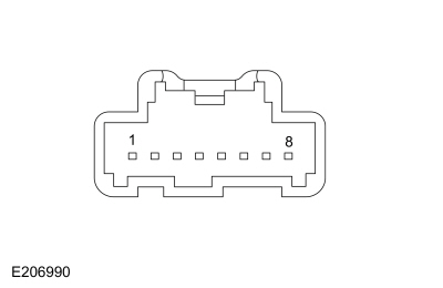
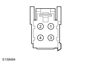
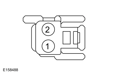
For circuit and connector information, refer to Cell 120 in the Wiring Diagrams.

Normal Operation and Fault Symptoms

REFER TO: Front Seats - System Operation and Component Description (501-10A Front Seats, Description and Operation).

Possible Sources

  • Fuse
  • Wiring, Terminals or Connectors
  • Seat Control Switch
  • Seat Track

Visual Inspection and Pre-checks

  • Make sure that fuse BJB 30 (30A) is in good condition.
WARNING: Incorrect repair methods or actions may cause unintentional deployment of the supplemental restraint system (SRS). Never compromise or deviate from these instructions. Failure to follow all instructions exactly may result in serious injury due to unintentional deployment.
A1 CHECK SEAT OPERATION
  • Attempt to operate the seat in all directions.

Seat does not operate in all directions?
Yes GO to A2
No If only the horizontal motor is inoperative, GO to A4.
If only the front height motor is inoperative, GO to A6.
If only the rear height motor is inoperative, GO to A8.
A2 CHECK THE VOLTAGE AT THE SEAT CONTROL SWITCH

  • REFER TO: Disabling the Supplemental Restraint System (SRS) (501-20B Supplemental Restraint System, General Procedures).
  • Disconnect: Driver Side Air Bag C3333.
  • Disconnect: Driver Seat Switch C360.
  • Action:
    Click to display the connectors
    Positive lead Measurement/Action Negative lead
    C360-9 Ground

Is the voltage greater than 11 volts?
Yes GO to A3
No CHECK the BJB fuse 30 (30A) for continuity. If OK, REPAIR the circuit. If not OK, REFER to the Wiring Diagrams Manual to determine possible causes of the short. GO to A10
A3 CHECK THE SEAT SWITCH GROUND CIRCUIT
  • Action:
    Click to display the connectors
    Positive lead Measurement/Action Negative lead
    C360-7 Ground

Is the resistance less than 3 ohms?
Yes INSTALL a new driver seat control switch.
REFER TO: Front Seat Control Switch (501-10A Front Seats, Removal and Installation).
GO to A10
No REPAIR the circuit. GO to A10
A4 CHECK THE VOLTAGE AT THE HORIZONTAL SEAT MOTOR

  • REFER TO: Disabling the Supplemental Restraint System (SRS) (501-20B Supplemental Restraint System, General Procedures).
  • Disconnect: Driver Side Air Bag C3333.
  • Disconnect: Driver Seat Horizontal Motor C362.
  • NOTE: The measured voltage changes polarity depending on the direction the seat control switch is activated. While pressing the horizontal switch forward and backward, measure:
    Click to display connectors
    Positive lead Measurement/Action Negative lead
    C362-1 C362-3

Voltage exceeds 11 V when the seat control switch is moved in both directions?
Yes INSTALL a new driver seat track.
REFER TO: Front Seat Track (501-10A Front Seats, Removal and Installation).
GO to A10
No GO to A5
A5 CHECK THE HORIZONTAL SEAT MOTOR CIRCUIT FOR AN OPEN
  • Disconnect: Driver Seat Switch C360.
  • Action:
    Click to display the connectors
    Positive lead Measurement/Action Negative lead
    C360-6 C362-3
    C360-5 C362-1

Is the resistance less than 3 ohms?
Yes INSTALL a new driver seat control switch.
REFER TO: Front Seat Control Switch (501-10A Front Seats, Removal and Installation).
GO to A10
No REPAIR the faulty circuit. GO to A10
A6 CHECK THE VOLTAGE AT THE FRONT SEAT LIFT MOTOR

  • REFER TO: Disabling the Supplemental Restraint System (SRS) (501-20B Supplemental Restraint System, General Procedures).
  • Disconnect: Driver Side Air Bag C3333.
  • Disconnect: Driver Front Seat Height Motor C382.
  • NOTE: The measured voltage changes polarity depending on the direction the seat control switch is activated. While pressing the front height switch up and down, measure:
    Click to display connectors
    Positive lead Measurement/Action Negative lead
    C382-1 C382-3

Voltage exceeds 11 V when the seat control switch is moved in both directions?
Yes INSTALL a new driver seat track.
REFER TO: Front Seat Track (501-10A Front Seats, Removal and Installation).
GO to A10
No GO to A7
A7 CHECK THE FRONT SEAT HEIGHT POWER MOTOR CIRCUIT FOR AN OPEN
  • Disconnect: Driver Seat Switch C360.
  • Action:
    Click to display the connectors
    Positive lead Measurement/Action Negative lead
    C360-1 C382-3
    C360-2 C382-1

Is the resistance less than 3 ohms?
Yes INSTALL a new driver seat control switch.
REFER TO: Front Seat Control Switch (501-10A Front Seats, Removal and Installation).
GO to A10
No REPAIR the faulty circuit. GO to A10
A8 CHECK THE VOLTAGE AT THE REAR SEAT LIFT MOTOR

  • REFER TO: Disabling the Supplemental Restraint System (SRS) (501-20B Supplemental Restraint System, General Procedures).
  • Disconnect: Driver Side Air Bag C3333.
  • Disconnect: Driver Seat Height Motor C363.
  • NOTE: The measured voltage changes polarity depending on the direction the seat control switch is activated. While pressing the rear height switch up and down, measure:
    Click to display connectors
    Positive lead Measurement/Action Negative lead
    C363-1 C363-3

Voltage exceeds 11 V when the seat control switch is moved in both directions?
Yes INSTALL a new driver seat track.
REFER TO: Front Seat Track (501-10A Front Seats, Removal and Installation).
GO to A10
No GO to A9
A9 CHECK THE REAR SEAT HEIGHT MOTOR CIRCUIT FOR AN OPEN
  • Disconnect: Driver Seat Switch C360.
  • Action:
    Click to display the connectors
    Positive lead Measurement/Action Negative lead
    C360-8 C363-3
    C360-10 C363-1

Is the resistance less than 3 ohms?
Yes INSTALL a new driver seat control switch.
REFER TO: Front Seat Control Switch (501-10A Front Seats, Removal and Installation).
GO to A10
No REPAIR the faulty circuit. GO to A10
A10 SRS (SUPPLEMENTAL RESTRAINT SYSTEM) CHECK SUCCESSFULLY VERIFIED

  • REFER TO: Disabling the Supplemental Restraint System (SRS) (501-20B Supplemental Restraint System, General Procedures).
  • Connect: Driver Side Air Bag C3333.
  • Connect all previously disconnected connectors.

  • REFER TO: Supplemental Restraint System (SRS) Reconfiguration (501-20B Supplemental Restraint System, General Procedures).

Did the SRS verification pass?
Yes Repair is complete. RETURN the vehicle to the customer.
No
REFER TO: Supplemental Restraint System (SRS) (501-20B Supplemental Restraint System, Diagnosis and Testing).
DIAGNOSTIC PINPOINT TEST B: POWER SEAT INOPERATIVE OR INCORRECT OPERATION – PASSENGER, 4-WAY

For circuit and connector information, refer to Cell 120 in the Wiring Diagrams.

Normal Operation and Fault Symptoms

REFER TO: Front Seats - System Operation and Component Description (501-10A Front Seats, Description and Operation).

Possible Sources

  • Fuse
  • Wiring, Terminals or Connectors
  • Seat Control Switch
  • Seat Track

Visual Inspection and Pre-checks

  • Check that fuse BJB 31 (30A) is OK.
WARNING: Incorrect repair methods or actions may cause unintentional deployment of the supplemental restraint system (SRS). Never compromise or deviate from these instructions. Failure to follow all instructions exactly may result in serious injury due to unintentional deployment.
B1 CHECK THE SEAT OPERATION
  • Attempt to operate the seat in all directions.

Seat does not operate in all directions?
Yes GO to B2
No If only the horizontal motor is inoperative, GO to B4.
If only the height motor is inoperative, GO to B6.
B2 CHECK THE VOLTAGE AT THE SEAT CONTROL SWITCH

  • REFER TO: Disabling the Supplemental Restraint System (SRS) (501-20B Supplemental Restraint System, General Procedures).
  • Disconnect: Passenger Side Air Bag C3309.
  • Disconnect: Passenger Seat Control Switch C3395.
  • Action:
    Click to display the connectors
    Positive lead Measurement/Action Negative lead
    C3395-8 Ground

Is the voltage greater than 11 volts?
Yes GO to B3
No CHECK the BJB fuse 31 (30A) for continuity. If OK, REPAIR the circuit. If not OK, REFER to the Wiring Diagrams Manual to determine possible causes of the short. GO to B8
B3 CHECK THE SEAT SWITCH GROUND CIRCUIT
  • Action:
    Click to display the connectors
    Positive lead Measurement/Action Negative lead
    C3395-10 Ground

Is the resistance less than 3 ohms?
Yes INSTALL a new passenger seat control switch.
REFER TO: Front Seat Control Switch (501-10A Front Seats, Removal and Installation).
GO to B8
No REPAIR the circuit. GO to B8
B4 CHECK THE VOLTAGE AT THE HORIZONTAL SEAT MOTOR

  • REFER TO: Disabling the Supplemental Restraint System (SRS) (501-20B Supplemental Restraint System, General Procedures).
  • Disconnect: Passenger Side Air Bag C3309.
  • Disconnect: Passenger Seat Horizontal Motor C332.
  • NOTE: The measured voltage changes polarity depending on the direction the seat control switch is activated. While pressing the horizontal switch forward and backward, measure:
    Click to display connectors
    Positive lead Measurement/Action Negative lead
    C332-1 C332-3

Voltage exceeds 11 V when the seat control switch is moved in both directions?
Yes INSTALL a new driver seat track.
REFER TO: Front Seat Track (501-10A Front Seats, Removal and Installation).
GO to B8
No GO to B5
B5 CHECK THE HORIZONTAL SEAT MOTOR CIRCUIT FOR AN OPEN
  • Disconnect: Passenger Seat Control Switch C3190.
  • Action:
    Click to display the connectors
    Positive lead Measurement/Action Negative lead
    C3395-1 C332-3
    C3395-2 C332-1

Is the resistance less than 3 ohms?
Yes INSTALL a new passenger seat control switch.
REFER TO: Front Seat Control Switch (501-10A Front Seats, Removal and Installation).
GO to B8
No REPAIR the faulty circuit. GO to B8
B6 CHECK THE VOLTAGE AT THE SEAT LIFT MOTOR

  • REFER TO: Disabling the Supplemental Restraint System (SRS) (501-20B Supplemental Restraint System, General Procedures).
  • Disconnect: Passenger Side Air Bag C3309.
  • Disconnect: Passenger Seat Height Adjustment Motor C330.
  • NOTE: The measured voltage changes polarity depending on the direction the seat control switch is activated. While activating the height switch up and down, measure:
    Probe the connectors
    Positive lead Measurement/Action Negative lead
    C330-1 C330-3

Voltage exceeds 11 V when the seat control switch is moved in both directions?
Yes INSTALL a new passenger seat track.
REFER TO: Front Seat Track (501-10A Front Seats, Removal and Installation).
GO to B8
No GO to B7
B7 CHECK THE SEAT HEIGHT MOTOR CIRCUIT FOR AN OPEN
  • Disconnect: Passenger Seat Control Switch C3395.
  • Action:
    Click to display the connectors
    Positive lead Measurement/Action Negative lead
    C3395-5 C330-3
    C3395-6 C330-1

Is the resistance less than 3 ohms?
Yes INSTALL a new passenger seat control switch.
REFER TO: Front Seat Control Switch (501-10A Front Seats, Removal and Installation).
GO to B8
No REPAIR the faulty circuit. GO to B8
B8 SRS (SUPPLEMENTAL RESTRAINT SYSTEM) CHECK SUCCESSFULLY VERIFIED

  • REFER TO: Disabling the Supplemental Restraint System (SRS) (501-20B Supplemental Restraint System, General Procedures).
  • Connect: Passenger Side Air Bag C3309.
  • Connect all previously disconnected connectors.

  • REFER TO: Supplemental Restraint System (SRS) Reconfiguration (501-20B Supplemental Restraint System, General Procedures).

Did the SRS verification pass?
Yes Repair is complete. RETURN the vehicle to the customer.
No
REFER TO: Supplemental Restraint System (SRS) (501-20B Supplemental Restraint System, Diagnosis and Testing).
DIAGNOSTIC PINPOINT TEST C: POWER SEAT INOPERATIVE OR INCORRECT OPERATION – DRIVER, 8-WAY

For circuit and connector information, refer to Cell 120 in the Wiring Diagrams.

Normal Operation and Fault Symptoms

REFER TO: Front Seats - System Operation and Component Description (501-10A Front Seats, Description and Operation).

Possible Sources

  • Fuse
  • Wiring, Terminals or Connectors
  • Seat Control Switch
  • Seat Track

Visual Inspection and Pre-checks

  • Make sure that fuse BJB 30 (30A) is in good condition.
WARNING: Incorrect repair methods or actions may cause unintentional deployment of the supplemental restraint system (SRS). Never compromise or deviate from these instructions. Failure to follow all instructions exactly may result in serious injury due to unintentional deployment.
C1 CHECK THE SEAT OPERATION
  • Attempt to operate the seat in all directions.

Seat does not operate in all directions?
Yes GO to C2
No If only the horizontal motor is inoperative, GO to C4.
If only the front height motor is inoperative, GO to C6.
If only the rear height motor is inoperative, GO to C8.
If only the seat motor is inoperative, GO to C10.
C2 CHECK THE VOLTAGE AT THE SEAT CONTROL SWITCH

  • REFER TO: Disabling the Supplemental Restraint System (SRS) (501-20B Supplemental Restraint System, General Procedures).
  • Disconnect: Driver Side Air Bag C3333.
  • Disconnect: Driver Seat Control Switch C3387.
  • Action:
    Click to display the connectors
    Positive lead Measurement/Action Negative lead
    C3387-10 Ground

Is the voltage greater than 11 volts?
Yes GO to C3
No CHECK the BJB fuse 30 (30A) for continuity. If OK, REPAIR the circuit. If not OK, REFER to the Wiring Diagrams Manual to determine possible causes of the short. GO to C12
C3 CHECK THE SEAT SWITCH GROUND CIRCUIT
  • Action:
    Click to display the connectors
    Positive lead Measurement/Action Negative lead
    C3387-11 Ground

Is the resistance less than 3 ohms?
Yes INSTALL a new driver seat control switch.
REFER TO: Front Seat Control Switch (501-10A Front Seats, Removal and Installation).
GO to C12
No REPAIR the circuit. GO to C12
C4 CHECK THE VOLTAGE AT THE HORIZONTAL SEAT MOTOR

  • REFER TO: Disabling the Supplemental Restraint System (SRS) (501-20B Supplemental Restraint System, General Procedures).
  • Disconnect: Driver Side Air Bag C3333.
  • Disconnect: Driver Seat Horizontal Motor C362.
  • NOTE: The measured voltage changes polarity depending on the direction the seat control switch is activated. While pressing the horizontal switch forward and backward, measure:
    Click to display connectors
    Positive lead Measurement/Action Negative lead
    C362-1 C362-3

Voltage exceeds 11 V when the seat control switch is moved in both directions?
Yes INSTALL a new driver seat track.
REFER TO: Front Seat Track (501-10A Front Seats, Removal and Installation).
GO to C12
No GO to C5
C5 CHECK THE SEAT FORE/AFT MOTOR CIRCUIT FOR AN OPEN
  • Disconnect: Driver Seat Control Switch C3387.
  • Action:
    Click to display the connectors
    Positive lead Measurement/Action Negative lead
    C3387-14 C362-3
    C3387-15 C362-1

Is the resistance less than 3 ohms?
Yes INSTALL a new driver seat control switch.
REFER TO: Front Seat Control Switch (501-10A Front Seats, Removal and Installation).
GO to C12
No REPAIR the faulty circuit. GO to C12
C6 CHECK THE VOLTAGE AT THE FRONT SEAT LIFTER MOTOR

  • REFER TO: Disabling the Supplemental Restraint System (SRS) (501-20B Supplemental Restraint System, General Procedures).
  • Disconnect: Driver Side Air Bag C3333.
  • Disconnect: Driver Front Seat Height Motor C382.
  • NOTE: The measured voltage changes polarity depending on the direction the seat control switch is activated. While pressing the front height switch up and down, measure:
    Click to display connectors
    Positive lead Measurement/Action Negative lead
    C382-1 C382-3

Voltage exceeds 11 volts when the seat control switch is moved in both directions?
Yes INSTALL a new driver seat track.
REFER TO: Front Seat Track (501-10A Front Seats, Removal and Installation).
GO to C12
No GO TO C7
C7 CHECK THE FRONT SEAT HEIGHT MOTOR CIRCUIT FOR AN OPEN
  • Disconnect: Driver Seat Control Switch C3387.
  • Action:
    Click to display the connectors
    Positive lead Measurement/Action Negative lead
    C3387-16 C382-3
    C3387-17 C382-1

Is the resistance less than 3 ohms?
Yes INSTALL a new driver seat control switch.
REFER TO: Front Seat Control Switch (501-10A Front Seats, Removal and Installation).
GO to C12
No REPAIR the faulty circuit. GO to C12
C8 CHECK THE VOLTAGE AT THE REAR SEAT LIFTER MOTOR

  • REFER TO: Disabling the Supplemental Restraint System (SRS) (501-20B Supplemental Restraint System, General Procedures).
  • Disconnect: Driver Side Air Bag C3333.
  • Disconnect: Driver Seat Height Motor C363.
  • NOTE: The measured voltage changes polarity depending on the direction the seat control switch is activated. While pressing the rear height switch up and down, measure:
    Click to display connectors
    Positive lead Measurement/Action Negative lead
    C363-1 C363-3

Voltage exceeds 11 V when the seat control switch is moved in both directions?
Yes INSTALL a new driver seat track.
REFER TO: Front Seat Track (501-10A Front Seats, Removal and Installation).
GO to C12
No GO TO C9
C9 CHECK THE REAR SEAT HEIGHT MOTOR CIRCUIT FOR AN OPEN
  • Disconnect: Driver Seat Control Switch C3387.
  • Action:
    Click to display the connectors
    Positive lead Measurement/Action Negative lead
    C3387-12 C363-3
    C3387-13 C363-1

Is the resistance less than 3 ohms?
Yes INSTALL a new driver seat control switch.
REFER TO: Front Seat Control Switch (501-10A Front Seats, Removal and Installation).
GO to C12
No REPAIR the faulty circuit. GO to C12
C10 CHECK THE VOLTAGE AT THE SEAT RECLINER MOTOR

  • REFER TO: Disabling the Supplemental Restraint System (SRS) (501-20B Supplemental Restraint System, General Procedures).
  • Disconnect: Driver Side Air Bag C3333.
  • Disconnect: Driver Seat Recliner Motor C3187.
  • NOTE: The measured voltage changes polarity depending on the direction the seat control switch is activated. While pressing the horizontal switch forward and backward, measure:
    Click to display connectors
    Positive lead Measurement/Action Negative lead
    C3187-1 C3187-3

Voltage exceeds 11 V when the seat control switch is moved in both directions?
Yes INSTALL a new driver seat track.
REFER TO: Front Seat Track (501-10A Front Seats, Removal and Installation).
GO to C12
No GO TO C11
C11 CHECK THE SEAT FORE/AFT MOTOR CIRCUIT FOR AN OPEN
  • Disconnect: Driver Seat Control Switch C3387.
  • Action:
    Click to display the connectors
    Positive lead Measurement/Action Negative lead
    C3387-7 C3187-3
    C3387-9 C3187-1

Is the resistance less than 3 ohms?
Yes INSTALL a new driver seat control switch.
REFER TO: Front Seat Control Switch (501-10A Front Seats, Removal and Installation).
GO to C12
No REPAIR the faulty circuit. GO to C12
C12 SRS (SUPPLEMENTAL RESTRAINT SYSTEM) CHECK PASSED

  • REFER TO: Disabling the Supplemental Restraint System (SRS) (501-20B Supplemental Restraint System, General Procedures).
  • Connect: Driver Side Air Bag C3333.
  • Connect all previously disconnected connectors.

  • REFER TO: Supplemental Restraint System (SRS) Reconfiguration (501-20B Supplemental Restraint System, General Procedures).

Did the SRS verification pass?
Yes Repair is complete. RETURN the vehicle to the customer.
No
REFER TO: Supplemental Restraint System (SRS) (501-20B Supplemental Restraint System, Diagnosis and Testing).
DIAGNOSTIC PINPOINT TEST D: POWER SEAT INOPERATIVE OR INCORRECT OPERATION – DRIVER, 10-WAY, NO MEMORY

For circuit and connector information, refer to Cell 120 in the Wiring Diagrams.

Normal Operation and Fault Symptoms

REFER TO: Front Seats - System Operation and Component Description (501-10A Front Seats, Description and Operation).

Possible Sources

  • Fuse
  • Wiring, Terminals or Connectors
  • Seat Control Switch
  • Seat Track

Visual Inspection and Pre-checks

  • Make sure that fuse BJB 30 (30A) is in good condition.
WARNING: Incorrect repair methods or actions may cause unintentional deployment of the supplemental restraint system (SRS). Never compromise or deviate from these instructions. Failure to follow all instructions exactly may result in serious injury due to unintentional deployment.
D1 SEAT OPERATION CHECK
  • Attempt to operate the seat in all directions.

Seat does not operate in all directions?
Yes GO to D2
No If only the seat recliner motor is inoperative, GO to D4.
If only the fore/aft motor is inoperative, GO to D6.
If only the front height motor is inoperative, GO to D8.
If only the rear height motor is inoperative, GO to D10.
D2 CHECK THE VOLTAGE AT THE SEAT CONTROL SWITCH

  • REFER TO: Disabling the Supplemental Restraint System (SRS) (501-20B Supplemental Restraint System, General Procedures).
  • Disconnect: Driver Side Air Bag C3333.
  • Disconnect: Driver Seat Control Switch C3387.
  • Action:
    Click to display the connectors
    Positive lead Measurement/Action Negative lead
    C3387-10 Ground

Is the voltage greater than 11 volts?
Yes GO to D3
No CHECK fuse 30 (30A) in the BJB for integrity. If OK, REPAIR the circuit. If not OK, REFER to the Wiring Diagrams Manual to determine the possible causes of the short circuit. GO to D12
D3 CHECK THE SEAT SWITCH GROUND CIRCUIT
  • Action:
    Click to display the connectors
    Positive lead Measurement/Action Negative lead
    C3387-11 Ground

Is the resistance less than 3 ohms?
Yes INSTALL a new driver seat control switch.
REFER TO: Front Seat Control Switch (501-10A Front Seats, Removal and Installation).
GO to D12
No REPAIR the circuit. GO to D12
D4 CHECK THE VOLTAGE AT THE SEAT RECLINER MOTOR

  • REFER TO: Disabling the Supplemental Restraint System (SRS) (501-20B Supplemental Restraint System, General Procedures).
  • Disconnect: Driver Side Air Bag C3333.
  • Disconnect: Driver Seat Recliner Motor C3187.
  • NOTE: The measured voltage changes polarity depending on the direction the seat control switch is activated. While pressing the recliner switch forward and backward, measure:
    Click to display connectors
    Positive lead Measurement/Action Negative lead
    C3187-1 C3187-3

Voltage exceeds 11 V when the seat control switch is moved in both directions?
Yes INSTALL a new driver front seat back frame. GO to D12
No GO to D5
D5 CHECK THE SEAT RECLINER MOTOR CIRCUITS FOR AN OPEN
  • Disconnect: Driver Seat Control Switch C3387.
  • Action:
    Click to display the connectors
    Positive lead Measurement/Action Negative lead
    C3387-9 C3187-1
    C3387-7 C3187-3

Is the resistance less than 3 ohms?
Yes INSTALL a new driver seat control switch.
REFER TO: Front Seat Control Switch (501-10A Front Seats, Removal and Installation).
GO to D12
No REPAIR the faulty circuit. GO to D12
D6 CHECK THE VOLTAGE AT THE SEAT FORE/AFT MOTOR

  • REFER TO: Disabling the Supplemental Restraint System (SRS) (501-20B Supplemental Restraint System, General Procedures).
  • Disconnect: Driver Side Air Bag C3333.
  • Disconnect: Driver Seat Horizontal Motor C362.
  • NOTE: The measured voltage changes polarity depending on the direction the seat control switch is activated. While pressing the horizontal switch forward and backward, measure:
    Click to display connectors
    Positive lead Measurement/Action Negative lead
    C362-1 C362-3

Voltage exceeds 11 V when the seat control switch is moved in both directions?
Yes INSTALL a new driver seat track.
REFER TO: Front Seat Track (501-10A Front Seats, Removal and Installation).
GO to D12
No GO to D7
D7 CHECK THE SEAT FORE/AFT MOTOR CIRCUIT FOR AN OPEN
  • Disconnect: Driver Seat Control Switch C3387.
  • Action:
    Click to display the connectors
    Positive lead Measurement/Action Negative lead
    C3387-14 C362-3
    C3387-15 C362-1

Is the resistance less than 3 ohms?
Yes INSTALL a new driver seat control switch.
REFER TO: Front Seat Control Switch (501-10A Front Seats, Removal and Installation).
GO to D12
No REPAIR the faulty circuit. GO to D12
D8 CHECK THE VOLTAGE AT THE FRONT SEAT HEIGHT MOTOR

  • REFER TO: Disabling the Supplemental Restraint System (SRS) (501-20B Supplemental Restraint System, General Procedures).
  • Disconnect: Driver Side Air Bag C3333.
  • Disconnect: Driver Front Seat Height Motor C382.
  • NOTE: The measured voltage changes polarity depending on the direction the seat control switch is activated. While pressing the front height switch up and down, measure:
    Click to display connectors
    Positive lead Measurement/Action Negative lead
    C382-1 C382-3

Voltage exceeds 11 volts when the seat control switch is moved in both directions?
Yes INSTALL a new driver seat track.
REFER TO: Front Seat Track (501-10A Front Seats, Removal and Installation).
GO to D12
No GO to D9
D9 CHECK THE FRONT SEAT HEIGHT MOTOR CIRCUIT FOR AN OPEN
  • Disconnect: Driver Seat Control Switch C3387.
  • Action:
    Click to display the connectors
    Positive lead Measurement/Action Negative lead
    C3387-16 C382-3
    C3387-17 C382-1

Is the resistance less than 3 ohms?
Yes INSTALL a new driver seat control switch.
REFER TO: Front Seat Control Switch (501-10A Front Seats, Removal and Installation).
GO to D12
No REPAIR the faulty circuit. GO to D12
D10 CHECK THE VOLTAGE AT THE REAR SEAT LIFTER MOTOR

  • REFER TO: Disabling the Supplemental Restraint System (SRS) (501-20B Supplemental Restraint System, General Procedures).
  • Disconnect: Driver Side Air Bag C3333.
  • Disconnect: Driver Seat Rear Height Motor C372.
  • NOTE: The measured voltage changes polarity depending on the direction the seat control switch is activated. While pressing the rear height switch up and down, measure:
    Click to display connectors
    Positive lead Measurement/Action Negative lead
    C372-1 C372-3

Voltage exceeds 11 V when the seat control switch is moved in both directions?
Yes INSTALL a new driver seat track.
REFER TO: Front Seat Track (501-10A Front Seats, Removal and Installation).
GO to D12
No GO to D11
D11 CHECK THE REAR SEAT HEIGHT MOTOR CIRCUIT FOR AN OPEN
  • Disconnect: Driver Seat Control Switch C3387.
  • Action:
    Click to display the connectors
    Positive lead Measurement/Action Negative lead
    C3387-12 C372-3
    C3387-13 C372-1

Is the resistance less than 3 ohms?
Yes INSTALL a new driver seat control switch.
REFER TO: Front Seat Control Switch (501-10A Front Seats, Removal and Installation).
GO to D12
No REPAIR the faulty circuit. GO to D12
D12 SRS (SUPPLEMENTAL RESTRAINT SYSTEM) CHECK PASSED

  • REFER TO: Disabling the Supplemental Restraint System (SRS) (501-20B Supplemental Restraint System, General Procedures).
  • Connect: Driver Side Air Bag C3333.
  • Connect all previously disconnected connectors.

  • REFER TO: Supplemental Restraint System (SRS) Reconfiguration (501-20B Supplemental Restraint System, General Procedures).

Did the SRS verification pass?
Yes Repair is complete. RETURN the vehicle to the customer.
No
REFER TO: Supplemental Restraint System (SRS) (501-20B Supplemental Restraint System, Diagnosis and Testing).
DIAGNOSTIC PINPOINT TEST E: POWER SEAT INOPERATIVE OR INCORRECT OPERATION – PASSENGER, 8-WAY

For circuit and connector information, refer to Cell 120 in the Wiring Diagrams.

Normal Operation and Fault Symptoms

REFER TO: Front Seats - System Operation and Component Description (501-10A Front Seats, Description and Operation).

Possible Sources

  • Fuse
  • Wiring, Terminals or Connectors
  • Seat Control Switch
  • Seat Track
  • Seat Back

Visual Inspection and Pre-checks

  • Check that fuse BJB 31 (30A) is OK.
WARNING: Incorrect repair methods or actions may cause unintentional deployment of the supplemental restraint system (SRS). Never compromise or deviate from these instructions. Failure to follow all instructions exactly may result in serious injury due to unintentional deployment.
E1 SEAT OPERATION CHECK
  • Attempt to operate the seat in all directions.

Seat does not operate in all directions?
Yes GO to E2
No If only the seat recliner motor is inoperative, GO to E4.
If only the fore/aft motor is inoperative, GO to E6.
If only the rear height motor is inoperative, GO to E8.
E2 CHECK THE VOLTAGE AT THE SEAT CONTROL SWITCH

  • REFER TO: Disabling the Supplemental Restraint System (SRS) (501-20B Supplemental Restraint System, General Procedures).
  • Disconnect: Passenger Side Air Bag C3309.
  • Disconnect: Passenger Seat Control Switch C3388.
  • Action:
    Click to display the connectors
    Positive lead Measurement/Action Negative lead
    C3388-11 Ground

Is the voltage greater than 11 volts?
Yes GO to E3
No CHECK fuse 31 (30A) in the BJB for integrity. If OK, REPAIR the circuit. If not OK, REFER to the Wiring Diagrams Manual to determine the possible causes of the short circuit. GO to E10
E3 CHECK THE SEAT SWITCH GROUND CIRCUIT
  • Action:
    Click to display the connectors
    Positive lead Measurement/Action Negative lead
    C3388-10 Ground

Is the resistance less than 3 ohms?
Yes INSTALL a new passenger seat control switch.
REFER TO: Front Seat Control Switch (501-10A Front Seats, Removal and Installation).
GO to E10
No REPAIR the circuit. GO to E10
E4 CHECK THE VOLTAGE AT THE SEAT RECLINER MOTOR

  • REFER TO: Disabling the Supplemental Restraint System (SRS) (501-20B Supplemental Restraint System, General Procedures).
  • Disconnect: Passenger Side Air Bag C3309.
  • Disconnect: Passenger Seat Recline Motor C3189.
  • NOTE: The measured voltage changes polarity depending on the direction the seat control switch is activated. While pressing the recliner switch forward and backward, measure:
    Click to display connectors
    Positive lead Measurement/Action Negative lead
    C3189-1 C3189-3

Voltage exceeds 11 V when the seat control switch is moved in both directions?
Yes INSTALL a new passenger front seat back frame. GO to E10
No GO to E5
E5 CHECK THE SEAT RECLINER MOTOR CIRCUITS FOR AN OPEN
  • Disconnect: Passenger Seat Control Switch C3388.
  • Action:
    Click to display the connectors
    Positive lead Measurement/Action Negative lead
    C3388-1 C3189-3
    C3388-3 C3189-1

Is the resistance less than 3 ohms?
Yes INSTALL a new passenger seat control switch.
REFER TO: Front Seat Control Switch (501-10A Front Seats, Removal and Installation).
GO to E10
No REPAIR the faulty circuit. GO to E10
E6 CHECK THE VOLTAGE AT THE SEAT FORE/AFT MOTOR

  • REFER TO: Disabling the Supplemental Restraint System (SRS) (501-20B Supplemental Restraint System, General Procedures).
  • Disconnect: Passenger Side Air Bag C3309.
  • Disconnect: Passenger Seat Horizontal Motor C332.
  • NOTE: The measured voltage changes polarity depending on the direction the seat control switch is activated. While pressing the horizontal switch forward and backward, measure:
    Click to display connectors
    Positive lead Measurement/Action Negative lead
    C332-1 C332-3

Voltage exceeds 11 V when the seat control switch is moved in both directions?
Yes INSTALL a new passenger seat track.
REFER TO: Front Seat Track (501-10A Front Seats, Removal and Installation).
GO to E10
No GO to E7
E7 CHECK THE SEAT FORE/AFT MOTOR CIRCUIT FOR AN OPEN
  • Disconnect: Passenger Seat Control Switch C330.
  • Action:
    Click to display the connectors
    Positive lead Measurement/Action Negative lead
    C3388-17 C332-3
    C3388-16 C332-1

Is the resistance less than 3 ohms?
Yes INSTALL a new passenger seat control switch.
REFER TO: Front Seat Control Switch (501-10A Front Seats, Removal and Installation).
GO to E10
No REPAIR the faulty circuit. GO to E10
E8 CHECK THE VOLTAGE AT THE SEAT LIFTER MOTOR

  • REFER TO: Disabling the Supplemental Restraint System (SRS) (501-20B Supplemental Restraint System, General Procedures).
  • Disconnect: Passenger Side Air Bag C3309.
  • Disconnect: Passenger Seat Height Adjustment Motor C330.
  • NOTE: The measured voltage changes polarity depending on the direction the seat control switch is activated. While pressing the rear height switch up and down, measure:
    Click to display connectors
    Positive lead Measurement/Action Negative lead
    C330-1 C330-3

Voltage exceeds 11 V when the seat control switch is moved in both directions?
Yes INSTALL a new passenger seat track.
REFER TO: Front Seat Track (501-10A Front Seats, Removal and Installation).
GO to E10
No GO to E9
E9 CHECK THE SEAT HEIGHT MOTOR CIRCUIT FOR AN OPEN
  • Disconnect: Passenger Seat Control Switch C330.
  • Action:
    Click to display the connectors
    Positive lead Measurement/Action Negative lead
    C3388-18 C330-3
    C3388-19 C330-1

Is the resistance less than 3 ohms?
Yes INSTALL a new passenger seat control switch.
REFER TO: Front Seat Control Switch (501-10A Front Seats, Removal and Installation).
GO to E10
No REPAIR the faulty circuit. GO to E10
E10 SRS (SUPPLEMENTAL RESTRAINT SYSTEM) CHECK PASSED

  • REFER TO: Disabling the Supplemental Restraint System (SRS) (501-20B Supplemental Restraint System, General Procedures).
  • Connect: Passenger Side Air Bag C3309.
  • Connect all previously disconnected connectors.

  • REFER TO: Supplemental Restraint System (SRS) Reconfiguration (501-20B Supplemental Restraint System, General Procedures).

Did the SRS verification pass?
Yes Repair is complete. RETURN the vehicle to the customer.
No
REFER TO: Supplemental Restraint System (SRS) (501-20B Supplemental Restraint System, Diagnosis and Testing).
DIAGNOSTIC PINPOINT TEST F: POWER LUMBAR INOPERATIVE – DRIVER, NON-MULTI-CONTOUR SEATS

For circuit and connector information, refer to Cell 120 in the Wiring Diagrams.

Normal Operation and Fault Symptoms

REFER TO: Front Seats - System Operation and Component Description (501-10A Front Seats, Description and Operation).

Possible Sources

  • Wiring, Terminals or Connectors
  • Seat Control Switch
  • Front Seat Power Lumbar
WARNING: Incorrect repair methods or actions may cause unintentional deployment of the supplemental restraint system (SRS). Never compromise or deviate from these instructions. Failure to follow all instructions exactly may result in serious injury due to unintentional deployment.
F1 SEAT LUMBAR MOTOR VOLTAGE CHECK

  • REFER TO: Disabling the Supplemental Restraint System (SRS) (501-20B Supplemental Restraint System, General Procedures).
  • Disconnect: Driver Side Air Bag C3333.
  • Disconnect: Driver Seat Lumbar Support Motor C3215.
  • NOTE: The measured voltage changes polarity depending on the direction the seat control switch is activated. While activating the lumbar switch in both directions, measure:
    Probe the connectors
    Positive lead Measurement/Action Negative lead
    C3215-A C3215-B

Voltage exceeds 11 V when the seat control switch is moved in both directions?
Yes INSTALL a new driver seat power lumbar assembly.
REFER TO: Front Power Lumbar Seat Assembly - Vehicles Without: Multi-Contour Seats (501-10A Front Seats, Removal and Installation).
GO to F3
No GO to F2
F2 CHECK THE SEAT LUMBAR MOTOR CIRCUITS FOR AN OPEN
  • Disconnect: Driver Seat Control Switch C3387.
  • Action:
    Click to display the connectors
    Positive lead Measurement/Action Negative lead
    C3387-2 C3215-B
    C3387-6 C3215-A

Is the resistance less than 3 ohms?
Yes INSTALL a new driver seat control switch.
REFER TO: Front Seat Control Switch (501-10A Front Seats, Removal and Installation).
GO to F3
No REPAIR the faulty circuit. GO to F3
F3 SRS (SUPPLEMENTAL RESTRAINT SYSTEM) CHECK PASSED

  • REFER TO: Disabling the Supplemental Restraint System (SRS) (501-20B Supplemental Restraint System, General Procedures).
  • Connect: Driver Side Air Bag C3333.
  • Connect all previously disconnected connectors.

  • REFER TO: Supplemental Restraint System (SRS) Reconfiguration (501-20B Supplemental Restraint System, General Procedures).

Did the SRS verification pass?
Yes Repair is complete. RETURN the vehicle to the customer.
No
REFER TO: Supplemental Restraint System (SRS) (501-20B Supplemental Restraint System, Diagnosis and Testing).
DIAGNOSTIC PINPOINT TEST G: POWER LUMBAR INOPERATIVE – PASSENGER, NON-MULTI-CONTOUR SEATS

For circuit and connector information, refer to Cell 120 in the Wiring Diagrams.

Normal Operation and Fault Symptoms

REFER TO: Front Seats - System Operation and Component Description (501-10A Front Seats, Description and Operation).

Possible Sources

  • Wiring, Terminals or Connectors
  • Seat Control Switch
  • Front Seat Power Lumbar
WARNING: Incorrect repair methods or actions may cause unintentional deployment of the supplemental restraint system (SRS). Never compromise or deviate from these instructions. Failure to follow all instructions exactly may result in serious injury due to unintentional deployment.
G1 CHECK THE VOLTAGE AT THE SEAT LUMBAR MOTOR.

  • REFER TO: Disabling the Supplemental Restraint System (SRS) (501-20B Supplemental Restraint System, General Procedures).
  • Disconnect: Passenger Side Air Bag C3309.
  • Disconnect: Passenger Seat Lumbar Support Motor C3216.
  • NOTE: The measured voltage changes polarity depending on the direction the seat control switch is activated. While activating the lumbar switch in both directions, measure:
    Probe the connectors
    Positive lead Measurement/Action Negative lead
    C3216-A C3216-B

Voltage exceeds 11 V when the seat control switch is moved in both directions?
Yes INSTALL a new passenger seat power lumbar assembly.
REFER TO: Front Power Lumbar Seat Assembly - Vehicles Without: Multi-Contour Seats (501-10A Front Seats, Removal and Installation).
GO to G3
No GO to G2
G2 CHECK THE SEAT LUMBAR MOTOR CIRCUITS FOR AN OPEN
  • Disconnect: Passenger Seat Control Switch C3388.
  • Action:
    Click to display the connectors
    Positive lead Measurement/Action Negative lead
    C3388-20 C3216-B
    C3388-2 C3216-A

Is the resistance less than 3 ohms?
Yes INSTALL a new passenger seat control switch.
REFER TO: Front Seat Control Switch (501-10A Front Seats, Removal and Installation).
GO to G3
No REPAIR the faulty circuit. GO to G3
G3 SRS (SUPPLEMENTAL RESTRAINT SYSTEM) CHECK PASSED

  • REFER TO: Disabling the Supplemental Restraint System (SRS) (501-20B Supplemental Restraint System, General Procedures).
  • Connect: Passenger Side Air Bag C3309.
  • Connect all previously disconnected connectors.

  • REFER TO: Supplemental Restraint System (SRS) Reconfiguration (501-20B Supplemental Restraint System, General Procedures).

Did the SRS verification pass?
Yes Repair is complete. RETURN the vehicle to the customer.
No
REFER TO: Supplemental Restraint System (SRS) (501-20B Supplemental Restraint System, Diagnosis and Testing).
DIAGNOSTIC PINPOINT TEST H: MEMORY SEAT INOPERATIVE IN HORIZONTAL/VERTICAL/TILT CONTROL USING THE SEAT CONTROL SWITCH

For circuit diagrams and connector information, refer to Wiring Diagrams cell 123.

Normal Operation and Fault Symptoms

REFER TO: Front Seats - System Operation and Component Description (501-10A Front Seats, Description and Operation).

DTC Fault Trigger Conditions

Trouble Code Description Fault Trigger Condition
DSM B14C3:24 Rear Seat Height Down Switch: Stuck High Signal If the seat control switch is active for more than 2 minutes or is active during the self-test, the DSM sets this DTC.
DSM B14C4:24 Rear Seat Height Up Switch: Stuck High Signal If the seat control switch is active for more than 2 minutes or is active during the self-test, the DSM sets this DTC.
DSM B14CE:09 Horizontal Seat Motor Power: Component Failures If the current detected by the DSM is within the specified range, a fault code is set and the output is disabled.
DSM B14CE:11 Horizontal Seat Motor Output: Short to Ground If the current detected by the DSM is within the specified range, a fault code is set and the output is disabled.
DSM B14CE:12 Horizontal Seat Motor Output: Short to Battery If the current detected by the DSM is within the specified range, a fault code is set and the output is disabled.
DTC B14CE:13 Seat Fore/Aft Motor Output: Circuit Open If the current detected by the DSM is within the specified range, a fault code is set and the output is disabled.
DSM B14CF:11 Recline Seat Motor Output: Short to Ground If the current detected by the DSM is within the specified range, a fault code is set and the output is disabled.
DSM B14CF:12 Recline Seat Motor Output: Short to Battery If the current detected by the DSM is within the specified range, a fault code is set and the output is disabled.
DTC B14CF:13 Seat Tilt Motor Output: Open Circuit If the current detected by the DSM is within the specified range, a fault code is set and the output is disabled.
DSM B14D0:11 Seat Height/Recline Motor Output Signal: Short to Ground If the current detected by the DSM is within the specified range, a fault code is set and the output is disabled.
DSM B14D0:12 Seat Height/Recline Motor Output Signal: Short to Battery If the current detected by the DSM is within the specified range, a fault code is set and the output is disabled.
DTC B14D0:13 Seat Front Height/Tilt Motor Output Signal: Circuit Open If the current detected by the DSM is within the specified range, a fault code is set and the output is disabled.
DSM B14D2:11 Rear Seat Height Motor Output: Short to Ground If the current detected by the DSM is within the specified range, a fault code is set and the output is disabled.
DSM B14D2:12 Rear Seat Height Motor Output: Short to Battery If the current detected by the DSM is within the specified range, a fault code is set and the output is disabled.
DTC B14D2:13 Rear Seat Height Motor Output: Open Circuit If the current detected by the DSM is within the specified range, a fault code is set and the output is disabled.
DTC B1B96:24 Seat Slide Forward Switch: High Signal If the current detected by the DSM is within the specified range, a fault code is set and the output is disabled.
DTC B1B97:24 Seat Slide Rearward Switch: Stuck High Signal If the seat control switch is active for more than 2 minutes or is active during the self-test, the DSM sets this DTC.
DTC B1B98:24 Seat Recline Up Switch: Stuck High Signal If the seat control switch is active for more than 2 minutes or is active during the self-test, the DSM sets this DTC.
DTC B1B99:24 Seat Tilt Down Switch: Signal Constantly High If the seat control switch is active for more than 2 minutes or is active during the self-test, the DSM sets this DTC.
DTC B1C00:24 Seat Recline Up Switch: Stuck High Signal If the seat control switch is active for more than 2 minutes or is active during the self-test, the DSM sets this DTC.
DTC B1C01:24 Seat Tilt Down Switch: Signal Constantly High If the seat control switch is active for more than 2 minutes or is active during the self-test, the DSM sets this DTC.

Possible Sources

  • Fuse
  • Wiring, Terminals or Connectors
  • Seat Control Switch
  • Fore/Aft Motor
  • Seat Track
  • Seat Back
  • DSM

Visual Inspection and Pre-checks

  • Make sure that fuse BJB 30 (30A) is in good condition.
WARNING: Incorrect repair methods or actions may cause unintentional deployment of the supplemental restraint system (SRS). Never compromise or deviate from these instructions. Failure to follow all instructions exactly may result in serious injury due to unintentional deployment.
H1 OBTAIN THE DSM (DRIVER FRONT SEAT MODULE) DIAGNOSTIC TROUBLE CODES (DTCS)
  • The ignition is on.
  • Attempt to activate the seat control switch in all directions.
  • Using the diagnostic scan tool, perform a DSM self-test. If the diagnostic scan tool does not communicate with the DSM,
    REFER TO: Communication Network (418-00 Communication Network, Diagnosis and Testing).

Are any DSM diagnostic trouble codes (DTCs) present?
Yes For DTC B14C3:24, B14C4:24, B1B96:24, B1B97:24, B1B98:24, B1B99:24, B1C00:24 or B1C01:24, GO to H3.
For DTC B14CE:XX, B14CF:XX, B14D0:XX or B14D2:XX, GO to H9.
For information on all other diagnostic trouble codes (DTCs), REFER to the DSM DTC Chart.
No GO to H2
H2 CHECK THE DSM (DRIVER FRONT SEAT MODULE) SEAT CONTROL SWITCH PARAMETER IDENTIFICATION (PIDS)
  • Operate the seat control switch in all positions and monitor the following DSM seat control switch parameter identifications (PIDs) with the diagnostic scan tool:
    • Access the DSM and monitor the SEAT_TILT_DWN PID

    • Access the DSM and monitor the SEAT_TILT_UP PID

    • Access the DSM and monitor the SEAT_RECL_DWN PID

    • Access the DSM and monitor the SEAT_RECL_UP PID

    • Access the DSM and monitor the SEAT_HGT_DWN PID

    • Access the DSM and monitor the SEAT_HGT_UP PID

    • Access the DSM and monitor the SEAT_BCK_SW PID

    • Access the DSM and monitor the SEAT_FW_SW PID


Do the PID states match the switch positions?
Yes GO to H9
No GO to H3
H3 CHECK THE SEAT CONTROL SWITCH
  • Ignition OFF.
  • Disconnect: Driver Seat Control Switch C3387.
  • Perform the seat control switch component test.
    REFER TO Wiring Diagrams, Cell 149, for schematic and connector information.

Did the seat control switch pass the component test?
Yes GO to H4
No INSTALL a new seat control switch.
REFER TO: Front Seat Control Switch (501-10A Front Seats, Removal and Installation).
H4 CHECK THE VOLTAGE AT THE SEAT CONTROL SWITCH

  • REFER TO: Disabling the Supplemental Restraint System (SRS) (501-20B Supplemental Restraint System, General Procedures).
  • Disconnect: Driver Side Air Bag C3333.
  • Action:
    Click to display the connectors
    Positive lead Measurement/Action Negative lead
    C3387-10 Ground

Is the voltage greater than 11 volts?
Yes GO to H5
No REPAIR the circuit. GO to H37
H5 CHECK THE SEAT SWITCH GROUND CIRCUIT FOR AN OPEN
  • Action:
    Click to display the connectors
    Positive lead Measurement/Action Negative lead
    C3387-11 Ground

Is the resistance less than 3 ohms?
Yes GO to H6
No REPAIR the circuit. GO to H37
H6 CHECK THE CIRCUITS BETWEEN THE SEAT CONTROL SWITCH AND THE DSM (DRIVER FRONT SEAT MODULE) FOR A SHORT TO VOLTAGE
  • Disconnect: DSM C341A.
  • The ignition is on.
  • Action:
    Click to display the connectors
    Positive lead Measurement/Action Negative lead
    C3387-17 Ground
    C3387-16 Ground
    C3387-13 Ground
    C3387-12 Ground
    C3387-14 Ground
    C3387-15 Ground
    C3387-9 Ground
    C3387-7 Ground

Is there voltage present?
Yes REPAIR the faulty circuit. GO to H37
No GO to H7
H7 CHECK THE CIRCUITS BETWEEN THE SEAT CONTROL SWITCH AND THE DSM (DRIVER FRONT SEAT MODULE) FOR A SHORT TO GROUND
  • Action:
    Click to display the connectors
    Positive lead Measurement/Action Negative lead
    C3387-17 Ground
    C3387-16 Ground
    C3387-13 Ground
    C3387-12 Ground
    C3387-14 Ground
    C3387-15 Ground
    C3387-9 Ground
    C3387-7 Ground

Is the resistance greater than 10000 ohms?
Yes GO to H8
No REPAIR the faulty circuit. GO to H37
H8 CHECK THE CIRCUITS BETWEEN THE SEAT CONTROL SWITCH AND THE DSM (DRIVER FRONT SEAT MODULE) FOR AN OPEN
  • Action:
    Click to display the connectors
    Positive lead Measurement/Action Negative lead
    C3387-17 C341A-13
    C3387-16 C341A-14
    C3387-13 C341A-1
    C3387-12 C341A-2
    C3387-14 C341A-3
    C3387-15 C341A-4
    C3387-9 C341A-12
    C3387-7 C341A-11

Is the resistance greater than 10000 ohms?
Yes GO to H36
No REPAIR the faulty circuit. GO to H37
H9 CHECK THE SEAT OPERATION
  • Using the seat control switch, attempt to operate the seat in the following directions:
    • Front Height Up and Down
    • Rear Height Up and Down
    • Horizontal forward and rearward
    • Recline forward and rearward

Does the driver seat operate correctly?
Yes The condition is intermittent. CHECK for the cause of the intermittent concern, especially the contacts and terminals of electrical connectors that were disconnected. Do not install any new components at this time. Components must only be installed when directed to do so in a pinpoint test. REPAIR any wiring, terminal or connector faults found.
No If the seat does not move, GO to H10.
If front vertical seat movement does not occur, GO to H12.
If rear vertical seat movement does not occur, GO to H18.
If horizontal seat movement does not occur, GO to H24.
If seat recline does not occur, GO to H30.
H10 CHECK THE VOLTAGE AT THE DSM (DRIVER FRONT SEAT MODULE)

  • REFER TO: Disabling the Supplemental Restraint System (SRS) (501-20B Supplemental Restraint System, General Procedures).
  • Disconnect: Driver Side Air Bag C3333.
  • Disconnect: DSM C341C.
  • Action:
    Click to display the connectors
    Positive lead Measurement/Action Negative lead
    C341C-2 Ground

Is the voltage greater than 11 volts?
Yes GO to H11
No REPAIR the circuit. GO to H37
H11 CHECK THE DSM (DRIVER FRONT SEAT MODULE) GROUND CIRCUITS FOR AN OPEN
  • Disconnect: DSM C341C.
  • Action:
    Click to display the connectors
    Positive lead Measurement/Action Negative lead
    C341C-4 Ground
    C341C-5 Ground
    C341C-6 Ground

Is the resistance less than 3 ohms?
Yes GO to H36
No REPAIR the faulty circuit. GO to H37
H12 CHECK THE FRONT VERTICAL MOTOR CIRCUITS FOR A SHORT TO VOLTAGE

  • REFER TO: Disabling the Supplemental Restraint System (SRS) (501-20B Supplemental Restraint System, General Procedures).
  • Disconnect: Driver Side Air Bag C3333.
  • Disconnect: DSM C341B.
  • The ignition is on.
  • Action:
    Click to display the connectors
    Positive lead Measurement/Action Negative lead
    C341B-8 Ground
    C341B-16 Ground

Is there voltage present?
Yes GO to H13
No GO to H14
H13 CHECK THE FRONT VERTICAL MOTOR CIRCUITS FOR A SHORT TO VOLTAGE WITH THE ENGINE OFF
  • Ignition OFF.
  • Disconnect: Driver Front Seat Height Motor C383.
  • The ignition is on.
  • Action:
    Click to display the connectors
    Positive lead Measurement/Action Negative lead
    C341B-8 Ground
    C341B-16 Ground

Is there voltage present?
Yes REPAIR the faulty circuit. GO to H37
No INSTALL a new driver seat track.
REFER TO: Front Seat Track (501-10A Front Seats, Removal and Installation).
GO to H37
H14 CHECK THE FRONT VERTICAL MOTOR CIRCUITS FOR A SHORT TO GROUND
  • Ignition OFF.
  • Action:
    Click to display the connectors
    Positive lead Measurement/Action Negative lead
    C341B-8 Ground
    C341B-16 Ground

Is the resistance greater than 10000 ohms?
Yes GO to H16
No GO to H15
H15 CHECK THE FRONT VERTICAL MOTOR CIRCUITS FOR A SHORT TO GROUND WITH THE ENGINE OFF
  • Disconnect: Driver Front Seat Height Motor C383.
  • Action:
    Click to display the connectors
    Positive lead Measurement/Action Negative lead
    C341B-8 Ground
    C341B-16 Ground

Is the resistance greater than 10000 ohms?
Yes INSTALL a new driver seat track.
REFER TO: Front Seat Track (501-10A Front Seats, Removal and Installation).
GO to H37
No REPAIR the faulty circuit. GO to H37
H16 CHECK THE FRONT VERTICAL MOTOR CIRCUITS FOR AN OPEN
  • Disconnect: Driver Front Seat Height Motor C383.
  • Action:
    Click to display the connectors
    Positive lead Measurement/Action Negative lead
    C341B-8 C383-1
    C341B-16 C383-3

Is the resistance less than 3 ohms?
Yes GO to H17
No REPAIR the faulty circuit. GO to H37
H17 CHECK THE VOLTAGE AT THE FRONT VERTICAL MOTOR

NOTICE: The following step uses a test lamp to simulate normal circuit loads. Use only the Rotunda test lamp (SGT27000) or a 300 mA incandescent lamp. To prevent damage to connector terminals, use the Rotunda Flex Probe Kit to connect the test lamp probe to the vehicle. Do not use the test lamp probe directly on any connector.

  • Connect: DSM C341B.
  • The ignition is on.
  • Connect a 12-volt incandescent test lamp between:
    Click to display connectors
    Positive lead Measurement/Action Negative lead
    C383-1 C383-3
  • NOTE: With the seat motor electrical connector disconnected, the DSM may activate the seat motor output for approximately 500 ms and then turn off. Activate the seat control switch position (front height up and down) while observing the indicator lamp.

Does the test lamp illuminate momentarily when the seat control switch is activated in both directions?
Yes INSTALL a new driver seat track.
REFER TO: Front Seat Track (501-10A Front Seats, Removal and Installation).
GO to H37
No GO to H36
H18 CHECK THE REAR HEIGHT MOTOR CIRCUITS FOR A SHORT TO VOLTAGE

  • REFER TO: Disabling the Supplemental Restraint System (SRS) (501-20B Supplemental Restraint System, General Procedures).
  • Disconnect: Driver Side Air Bag C3333.
  • Disconnect: DSM C341B.
  • The ignition is on.
  • Action:
    Click to display the connectors
    Positive lead Measurement/Action Negative lead
    C341B-2 Ground
    C341B-5 Ground

Is there voltage present?
Yes GO to H19
No GO to H20
H19 CHECK THE REAR HEIGHT MOTOR CIRCUITS FOR A SHORT TO VOLTAGE WITH THE ENGINE OFF
  • Ignition OFF.
  • Disconnect: Driver Seat Height Motor C363.
  • The ignition is on.
  • Action:
    Click to display the connectors
    Positive lead Measurement/Action Negative lead
    C341B-2 Ground
    C341B-5 Ground

Is there voltage present?
Yes REPAIR the faulty circuit. GO to H37
No INSTALL a new driver seat track.
REFER TO: Front Seat Track (501-10A Front Seats, Removal and Installation).
GO to H37
H20 CHECK THE REAR HEIGHT MOTOR CIRCUITS FOR A SHORT TO GROUND
  • Ignition OFF.
  • Action:
    Click to display the connectors
    Positive lead Measurement/Action Negative lead
    C341B-2 Ground
    C341B-5 Ground

Is the resistance greater than 10000 ohms?
Yes GO to H22
No GO to H21
H21 CHECK THE REAR HEIGHT MOTOR CIRCUITS FOR A SHORT TO GROUND WITH THE ENGINE OFF
  • Disconnect: Driver Seat Height Motor C363.
  • Action:
    Click to display the connectors
    Positive lead Measurement/Action Negative lead
    C341B-2 Ground
    C341B-5 Ground

Is the resistance greater than 10000 ohms?
Yes INSTALL a new driver seat track.
REFER TO: Front Seat Track (501-10A Front Seats, Removal and Installation).
GO to H37
No REPAIR the faulty circuit. GO to H37
H22 CHECK THE REAR HEIGHT MOTOR CIRCUITS FOR AN OPEN
  • Disconnect: Driver Seat Height Motor C363.
  • Action:
    Click to display the connectors
    Positive lead Measurement/Action Negative lead
    C341B-2 C363-1
    C341B-5 C363-3

Is the resistance less than 3 ohms?
Yes GO to H23
No REPAIR the faulty circuit. GO to H37
H23 CHECK THE VOLTAGE AT THE REAR HEIGHT MOTOR

NOTICE: The following step uses a test lamp to simulate normal circuit loads. Use only the Rotunda test lamp (SGT27000) or a 300 mA incandescent lamp. To prevent damage to connector terminals, use the Rotunda Flex Probe Kit to connect the test lamp probe to the vehicle. Do not use the test lamp probe directly on any connector.

  • Connect: DSM C341B.
  • The ignition is on.
  • Connect a 12-volt incandescent test lamp between:
    Click to display connectors
    Positive lead Measurement/Action Negative lead
    C363-1 C363-3
  • NOTE: With the seat motor electrical connector disconnected, the DSM may activate the seat motor output for approximately 500 ms and then turn off. Activate the seat control switch positions (rear height up and down) while observing the indicator lamp.

Does the test lamp illuminate momentarily when the seat control switch is activated in both directions?
Yes INSTALL a new driver seat track.
REFER TO: Front Seat Track (501-10A Front Seats, Removal and Installation).
GO to H37
No GO to H36
H24 CHECK THE HORIZONTAL MOTOR CIRCUITS FOR A SHORT TO VOLTAGE

  • REFER TO: Disabling the Supplemental Restraint System (SRS) (501-20B Supplemental Restraint System, General Procedures).
  • Disconnect: Driver Side Air Bag C3333.
  • Disconnect: DSM C341B.
  • The ignition is on.
  • Action:
    Click to display the connectors
    Positive lead Measurement/Action Negative lead
    C341B-14 Ground
    C341B-15 Ground

Is there voltage present?
Yes GO to H25
No GO to H26
H25 CHECK THE HORIZONTAL MOTOR CIRCUITS FOR A SHORT TO VOLTAGE WITH THE ENGINE OFF
  • Ignition OFF.
  • Disconnect: Driver Seat Horizontal Motor C362.
  • The ignition is on.
  • Action:
    Click to display the connectors
    Positive lead Measurement/Action Negative lead
    C341B-14 Ground
    C341B-15 Ground

Is there voltage present?
Yes REPAIR the faulty circuit. GO to H37
No INSTALL a new driver seat track.
REFER TO: Front Seat Track (501-10A Front Seats, Removal and Installation).
GO to H37
H26 CHECK THE HORIZONTAL MOTOR CIRCUITS FOR A SHORT TO GROUND
  • Ignition OFF.
  • Action:
    Click to display the connectors
    Positive lead Measurement/Action Negative lead
    C341B-14 Ground
    C341B-15 Ground

Is the resistance greater than 10000 ohms?
Yes GO to H28
No GO to H27
H27 CHECK THE HORIZONTAL MOTOR CIRCUITS FOR A SHORT TO GROUND WITH THE ENGINE OFF
  • Disconnect: Driver Seat Horizontal Motor C362.
  • Action:
    Click to display the connectors
    Positive lead Measurement/Action Negative lead
    C341B-14 Ground
    C341B-15 Ground

Is the resistance greater than 10000 ohms?
Yes INSTALL a new driver seat track.
REFER TO: Front Seat Track (501-10A Front Seats, Removal and Installation).
GO to H37
No REPAIR the faulty circuit. GO to H37
H28 CHECK THE HORIZONTAL MOTOR CIRCUITS FOR AN OPEN
  • Disconnect: Driver Seat Horizontal Motor C362.
  • Action:
    Click to display the connectors
    Positive lead Measurement/Action Negative lead
    C341B-14 C362-1
    C341B-15 C362-3

Is the resistance less than 3 ohms?
Yes GO to H29
No REPAIR the faulty circuit. GO to H37
H29 CHECK THE VOLTAGE AT THE HORIZONTAL MOTOR

NOTICE: The following step uses a test lamp to simulate normal circuit loads. Use only the Rotunda test lamp (SGT27000) or a 300 mA incandescent lamp. To prevent damage to connector terminals, use the Rotunda Flex Probe Kit to connect the test lamp probe to the vehicle. Do not use the test lamp probe directly on any connector.

  • Connect: DSM C341B.
  • The ignition is on.
  • Connect a 12-volt incandescent test lamp between:
    Click to display connectors
    Positive lead Measurement/Action Negative lead
    C362-1 C362-3
  • NOTE: With the seat motor electrical connector disconnected, the DSM may activate the seat motor output for approximately 500 ms and then turn off. Activate the seat control switch position (horizontal forward and rearward) while observing the indicator lamp.

Does the test lamp illuminate momentarily when the seat control switch is activated in both directions?
Yes INSTALL a new driver seat track.
REFER TO: Front Seat Track (501-10A Front Seats, Removal and Installation).
GO to H37
No GO to H36
H30 CHECK THE RECLINER MOTOR CIRCUITS FOR A SHORT TO VOLTAGE

  • REFER TO: Disabling the Supplemental Restraint System (SRS) (501-20B Supplemental Restraint System, General Procedures).
  • Disconnect: Driver Side Air Bag C3333.
  • Disconnect: DSM C341B.
  • The ignition is on.
  • Action:
    Click to display the connectors
    Positive lead Measurement/Action Negative lead
    C341B-7 Ground
    C341B-4 Ground

Is there voltage present?
Yes GO to H31
No GO to H32
H31 CHECK THE FRONT VERTICAL MOTOR CIRCUITS FOR A SHORT TO VOLTAGE WITH THE SEAT MOTOR DISCONNECTED
  • Ignition OFF.
  • Disconnect: Driver Seat Front Tilt Motor C3187.
  • The ignition is on.
  • Action:
    Click to display the connectors
    Positive lead Measurement/Action Negative lead
    C341B-7 Ground
    C341B-4 Ground

Is there voltage present?
Yes REPAIR the faulty circuit. GO to H37
No INSTALL a new driver seat back frame. GO to H37
H32 CHECK THE FRONT VERTICAL MOTOR CIRCUITS FOR A SHORT TO GROUND
  • Ignition OFF.
  • Action:
    Click to display the connectors
    Positive lead Measurement/Action Negative lead
    C341B-7 Ground
    C341B-4 Ground

Is the resistance greater than 10000 ohms?
Yes GO to H34
No GO to H33
H33 CHECK THE RECLINER MOTOR CIRCUITS FOR A SHORT TO GROUND WITH THE ENGINE OFF
  • Disconnect: Driver Seat Recliner Motor C3187.
  • Action:
    Click to display the connectors
    Positive lead Measurement/Action Negative lead
    C341B-7 Ground
    C341B-4 Ground

Is the resistance greater than 10000 ohms?
Yes INSTALL a new driver seat back frame. GO to H37
No REPAIR the faulty circuit. GO to H37
H34 CHECK THE RECLINER MOTOR CIRCUITS FOR AN OPEN
  • Disconnect: Driver Seat Recliner Motor C3187.
  • Action:
    Click to display the connectors
    Positive lead Measurement/Action Negative lead
    C341B-7 C3187-1
    C341B-4 C3187-3

Is the resistance less than 3 ohms?
Yes GO to H35
No REPAIR the faulty circuit. GO to H37
H35 CHECK THE VOLTAGE AT THE RECLINER MOTOR

NOTICE: The following step uses a test lamp to simulate normal circuit loads. Use only the Rotunda test lamp (SGT27000) or a 300 mA incandescent lamp. To prevent damage to connector terminals, use the Rotunda Flex Probe Kit to connect the test lamp probe to the vehicle. Do not use the test lamp probe directly on any connector.

  • Connect: DSM C341B.
  • The ignition is on.
  • Connect a 12-volt incandescent test lamp between:
    Click to display connectors
    Positive lead Measurement/Action Negative lead
    C3187-1 C3187-3
  • NOTE: With the seat motor electrical connector disconnected, the DSM may activate the seat motor output for approximately 500 ms and then turn off. Activate the seat control switch position (recline forward and rearward) while observing the indicator lamp.

Does the test lamp illuminate momentarily when the seat control switch is activated in both directions?
Yes INSTALL a new driver seat back frame. GO to H37
No GO to H36
H36 CHECK THE DSM (DRIVER FRONT SEAT MODULE) OPERATION
  • Ignition OFF.
  • Disconnect and inspect all DSM connectors.
  • Repair:
    • corrosion (install new connector or terminals - clean module pins)
    • damaged or bent pins - if necessary, install new terminals/pins
    • pushed-out pins - install new pins as necessary
  • Reconnect the DSM connectors. Make sure they are fully seated and locked.
  • NOTE: Do not connect the driver side airbag module C3333 at this time. Connect all previously disconnected connectors.
  • The ignition is on.
  • Operate the system and determine if the concern is still present.

Is the concern still present?
Yes CHECK OASIS for any applicable service articles: TSB, GSB, SSM or FSA. If a service article exists for this concern, STOP this test and FOLLOW the service article instructions. If no service articles exist for this concern, INSTALL a new DSM.
REFER TO: Driver Seat Module (DSM) (501-10A Front Seats, Removal and Installation).
GO to H37
No The system is currently operating correctly. The concern may have been caused by module connections. CHECK for root cause of any connector or terminal concerns. GO to H37
H37 SRS (SUPPLEMENTAL RESTRAINT SYSTEM) CHECK SUCCESSFULLY COMPLETED

  • REFER TO: Disabling the Supplemental Restraint System (SRS) (501-20B Supplemental Restraint System, General Procedures).
  • Connect: Driver Side Air Bag C3333.
  • Connect all previously disconnected connectors.

  • REFER TO: Supplemental Restraint System (SRS) Reconfiguration (501-20B Supplemental Restraint System, General Procedures).

Did the SRS verification pass?
Yes Repair is complete. RETURN the vehicle to the customer.
No
REFER TO: Supplemental Restraint System (SRS) (501-20B Supplemental Restraint System, Diagnosis and Testing).
DIAGNOSTIC PINPOINT TEST I: MEMORY SEAT INOPERATIVE USING THE MEMORY SET SWITCH

For circuit diagrams and connector information, refer to Wiring Diagrams cell 123.

Normal Operation and Fault Symptoms

REFER TO: Front Seats - System Operation and Component Description (501-10A Front Seats, Description and Operation).

DTC Fault Trigger Conditions

Trouble Code Description Fault Trigger Condition
DDM B1C03:23 Memory Switch No. 1: Low Signal If a short to ground is detected in the switch input circuit during the DDM self-test, a DTC is set. If activity is detected on the input circuit for more than 2 minutes, the DTC is set as continuous. While a DTC is set, any input signal on the circuit is ignored.
DDM B1C04:23 Memory Switch No. 2: Low Signal If a short to ground is detected in the switch input circuit during the DDM self-test, a DTC is set. If activity is detected on the input circuit for more than 2 minutes, the DTC is set as continuous. While a DTC is set, any input signal on the circuit is ignored.
DDM B1C05:23 Memory Switch No. 3: Low Signal If a short to ground is detected in the switch input circuit during the DDM self-test, a DTC is set. If activity is detected on the input circuit for more than 2 minutes, the DTC is set as continuous. While a DTC is set, any input signal on the circuit is ignored.

Possible Sources

  • Memory seat hard/soft stops installed incorrectly
  • Wiring, Terminals or Connectors
  • SET memory switch
  • Ignition status information is missing
  • DDM
WARNING: Incorrect repair methods or actions may cause unintentional deployment of the supplemental restraint system (SRS). Never compromise or deviate from these instructions. Failure to follow all instructions exactly may result in serious injury due to unintentional deployment.
I1 CHECK DSM (DRIVER SEAT MODULE) IGNITION STATE PID (PARAMETER IDENTIFICATION)
  • The ignition is on.
  • Access the BCM and monitor the IGN_SW_STATE PID

  • Monitor the PID while cycling the ignition from ON to OFF and back to ON.

Do the PID states agree?
Yes GO to I2.
No To diagnose no power during operation,
REFER TO: Steering Wheel and Column Electrical Components (211-05 Steering Wheel and Column Electrical Components, Diagnosis and Testing).
I2 CHECK DIAGNOSTIC TROUBLE CODES (DTCS)
  • Using a diagnostic scan tool, perform a self-test of the DSM and DDM. If the diagnostic scan tool does not communicate with the DSM and/or DDM,
    REFER TO: Communication Network (418-00 Communication Network, Diagnosis and Testing).

Are any diagnostic trouble codes (DTCs) present?
Yes For DTC B1C03:23, B1C04:23 or B1C05:23, GO to I4.
For information on all other diagnostic trouble codes (DTCs), REFER TO the DSM or DDM DTC chart(s) in this section.
No GO to I3
I3 MONITOR DDM (DRIVER DOOR MODULE) PARAMETER IDENTIFICATION (PIDS) AND CHECK MEMORY SETTING SWITCH INPUTS
  • While activating memory recall buttons 1, 2 and 3, monitor the following DDM memory recall switch parameter identifications (PIDs) with the diagnostic scan tool:
    • Access the DDM and monitor the MEMORY_SW_1 PID

    • Access the DDM and monitor the MEMORY_SW_2 PID

    • Access the DDM and monitor the MEMORY_SW_3 PID


Do the PID values match the switch button positions?
Yes Using the seat control switch, OPERATE the memory seat through the full travel of each seat axis to reset the hard/soft stops. Run the system and determine if the concern persists. If the seat malfunctions in any direction, GO to the pinpoint test H
No GO to I4
I4 CHECK MEMORY SETTING SWITCH
  • Ignition OFF.
  • Disconnect: Driver Door Lock Switch C541.
  • Press and release the specified memory recall button 1, and measure the component side resistance of the driver door lock control switch using the following table:
    Positive lead Measurement/Action Negative lead
    C541, Pin 5, component side C541, Pin 6, component side
  • Press and release the specified memory recall button 2, and measure the component side resistance of the driver door lock control switch using the following table:
    Positive lead Measurement/Action Negative lead
    C541, Pin 4, component side C541, Pin 6, component side
  • Press and release the specified memory recall button 3, and measure the component side resistance of the driver door lock control switch using the following table:
    Positive lead Measurement/Action Negative lead
    C541, Pin 3, component side C541, Pin 6, component side

Is the resistance less than 20 ohms with the switch buttons pressed and greater than 10,000 ohms with the switch buttons released?
Yes GO to I5
No INSTALL a new driver door lock control switch.
REFER TO: Front Door Lock Control Switch (501-14 Handles, Locks, Latches and Entry Systems, Removal and Installation).
I5 CHECK MEMORY SWITCH GROUND CIRCUIT FOR OPEN
  • Ignition OFF.
  • Disconnect: DDM C501A.
  • Action:
    Click to display the connectors
    Positive lead Measurement/Action Negative lead
    C541-6 C501A-10

Is the resistance less than 3 ohms?
Yes GO to I6
No REPAIR the circuit.
I6 CHECK MEMORY CIRCUITS FOR SHORT TO VOLTAGE
  • The ignition is on.
  • Action:
    Click to display the connectors
    Positive lead Measurement/Action Negative lead
    C541-3 Ground
    C541-4 Ground
    C541-5 Ground

Is there voltage present?
Yes REPAIR the faulty circuit.
No GO to I7
I7 CHECK MEMORY MODULE SWITCH CIRCUITS FOR SHORT TO GROUND
  • Ignition OFF.
  • Action:
    Click to display the connectors
    Positive lead Measurement/Action Negative lead
    C541-3 Ground
    C541-4 Ground
    C541-5 Ground

Is the resistance greater than 10000 Ohms?
Yes GO to I8
No REPAIR the faulty circuit.
I8 CHECK MEMORY SWITCH CIRCUITS FOR OPEN
  • Action:
    Click to display the connectors
    Positive lead Measurement/Action Negative lead
    C541-3 C501A-17
    C541-4 C501A-16
    C541-5 C501A-15

Is the resistance less than 3 ohms?
Yes GO to I9
No REPAIR the faulty circuit.
I9 CHECK DDM (DRIVER DOOR MODULE) OPERATION
  • Ignition OFF.
  • Disconnect and inspect all DDM connectors.
  • Repair:
    • corrosion (install new connector or terminals - clean module pins)
    • damaged or bent pins - if necessary, install new terminals/pins
    • pushed-out pins - install new pins as necessary
  • Reconnect the DDM connectors. Make sure they are fully seated and properly latched.
  • The ignition is on.
  • Operate the system and determine if the concern is still present.

Is the concern still present?
Yes CHECK OASIS for any applicable service articles: TSB, GSB, SSM or FSA. If a service article exists for this concern, STOP this test and FOLLOW the service article instructions. If no service articles exist for this concern, INSTALL a new DDM.
REFER TO: Driver Door Module (DDM) (419-10 Multifunction Electronic Modules, Removal and Installation).
No The system is currently operating correctly. The concern may have been caused by module connections. ADDRESS the root cause of any connector or terminal issues.
DIAGNOSTIC PINPOINT TEST J: EASY ENTRY/EASY EXIT INOPERATIVE/INCORRECT OPERATION

Normal Operation and Fault Symptoms

REFER TO: Front Seats - System Operation and Component Description (501-10A Front Seats, Description and Operation).

Possible Sources

  • Easy entry/exit function is not enabled
  • Ignition status information is missing
  • DSM

Visual Inspection and Pre-checks

  • Make sure the Easy Entry/Exit feature is enabled in the Message Center. REFER TO the Owner's Literature for information on programming vehicle settings in the Message Center.
J1 CHECK DRIVER POWER SEAT OPERATION
  • The ignition is on.
  • Check the Message Center to make sure the Easy Entry/Exit feature is enabled.
  • Using the seat control switch, check that the power driver seat moves fully forward and rearward.
  • Using the scan tool, perform the DSM self-test.

Are any Diagnostic Trouble Codes (DTCs) retrieved?
Yes REFER TO the DSM DTC chart.
No If disabled, ENABLE the easy entry/exit feature through the message center. REFER TO the Owner's Literature. CHECK the system for normal operation. If correct, INSTRUCT the customer on proper system operation. GO to J2
J2 CHECK DSM (DRIVER SEAT MODULE) IGNITION STATE PID (PARAMETER IDENTIFICATION)
  • The ignition is on.
  • Access the BCM and monitor the IGN_SW_STATE PID

  • Monitor the PID while cycling the ignition from ON to OFF and back to ON.

Do the PID states match the ignition mode?
Yes INSTALL a new DSM.
REFER TO: Driver Seat Module (DSM) (501-10A Front Seats, Removal and Installation).
No CHECK the ignition state.
REFER TO: Steering Wheel and Column Electrical Components (211-05 Steering Wheel and Column Electrical Components, Diagnosis and Testing).
DIAGNOSTIC PINPOINT TEST K: DTC: U0140:00

For circuit and connector information, refer to Wiring Diagrams Cell 14.

Normal Operation and Fault Symptoms

The DSM and BCM communicate using MS-CAN.

DTC Fault Trigger Conditions

Trouble Code Description Fault Trigger Condition
DSM U0140:00 Lost Communication With Body Control Module: No Sub Type Information The DSM sets whenever it loses communication with the BCM for 5 seconds or longer, while the DSM input voltage is between 10 and 15.5 volts.

Possible Sources

  • Communication Module
  • DSM
  • BCM
K1 CONFIRM THE CUSTOMER CONCERN
  • The ignition is on.
  • Make sure the observed symptom is present.

Is the observed symptom present?
Yes GO to K2
No The system is currently operating normally. The DTC may have been set due to high network traffic or an intermittent condition.
K2 CHECK THE COMMUNICATION NETWORK
  • The ignition is on.
  • Using a scan tool, perform the network test.

Does the BCM pass the network test?
Yes GO to K3
No
REFER TO: Communication Network (418-00 Communication Network, Diagnosis and Testing).
K3 RECHECK THE DSM (DRIVER SEAT MODULE) DIAGNOSTIC TROUBLE CODES (DTCS)
  • Using the scan tool, clear the Continuous Memory Diagnostic Trouble Codes (CMDTCs).
  • Using the scan tool, repeat the DSM self-test.

Is DTC U0140:00 still present?
Yes GO to K4
No The system is currently operating correctly. The DTC may have been set due to high network traffic or an intermittent condition.
K4 CHECK DTC U0140:00 IN OTHER MODULES
  • Using the scan tool, clear the Continuous Memory Diagnostic Trouble Codes (CMDTCs).
  • Ignition OFF.
  • The ignition is on.
  • Wait 10 seconds.
  • Using a diagnostic scan tool, retrieve Continuous Memory Diagnostic Trouble Codes (CMDTCs) from all modules.

Is DTC U0140:00 set in any other modules?
Yes INSTALL a new BCM.
REFER TO: Body Control Module (BCM) (419-10 Multifunction Electronic Modules, Removal and Installation).
No INSTALL a new DSM.
REFER TO: Driver Seat Module (DSM) (501-10A Front Seats, Removal and Installation).
DIAGNOSTIC PINPOINT TEST L: MULTI-CONTOUR SEAT INOPERATIVE / INCORRECT OPERATION – DRIVER

For circuit diagrams and connector information, refer to Wiring Diagrams cell 123.

Normal Operation and Fault Symptoms

REFER TO: Front Seats - System Operation and Component Description (501-10A Front Seats, Description and Operation).

DTC Fault Trigger Conditions

Trouble Code Description Fault Trigger Condition
SCMG B146F: 00 Rear Bladder Electro-Pneumatic Malfunction: No Subtype Information During the self-test, the system inflates each bladder in the seat back, then monitors the pressure change. If the pressure change is not within the acceptable threshold, this DTC is set.
SCMG B146F: 04 Rear Bladder Electro-Pneumatic Failure: Internal System Failures During the self-test, the system inflates each bladder in the seat back, then monitors the pressure change. If the bladders inflate successfully, the system deflates the bladder and monitors the pressure change. If the pressure change is outside the acceptable threshold, this DTC is set.
SCMG B1470:00 Electro-Pneumatic Bladder System Fault: No Sub-type Information During the self-test, the system inflates each bladder in the seat cushion, then monitors the pressure change. If the pressure change is not within the acceptable threshold, this DTC is set.
DTC B1470:04 Electro-Pneumatic Bladder System Fault: Internal System Faults During the self-test, the system inflates each bladder in the seat cushion, then monitors the pressure change. If the bladders inflate successfully, the system deflates the bladder and monitors the pressure change. If the pressure change is outside the acceptable threshold, this DTC is set.
SCMG B1471:11 Multi-Contour Seat Switch Input: Short to Ground This DTC is set when the multi-contour seat control switch input circuit is shorted to ground. This DTC may be set on demand or in continuous memory.
SCMG B1471:13 Multi-Contour Seat Switch Input: Open Circuit This DTC is set when the multi-contour seat control switch input circuit is open. This DTC may be set on demand or in continuous memory.
DTC B1471:2A Multi-Contour Seat Switch Input: Stuck in Range If the seat control switch is active for more than 2 minutes or is active during the self-test, the SCMG sets this DTC.
SCMG B1473:11 Pump Driver: Short to Ground This DTC is set when the current draw of the air pump driver is too high for a specified period of time. This DTC may be set on demand or in continuous memory.

Possible Sources

  • Wiring, Terminals or Connectors
  • Seat Control Switch
  • Front Seat Power Lumbar
  • Front Seat Cushion Bladder
  • SCMG

Visual Inspection and Pre-checks

  • Make sure all hose connections to the SCMG are installed correctly and are not leaking, and/or check for any signs of restriction (kinked or pinched hoses).
WARNING: Incorrect repair methods or actions may cause unintentional deployment of the supplemental restraint system (SRS). Never compromise or deviate from these instructions. Failure to follow all instructions exactly may result in serious injury due to unintentional deployment.
L1 CHECK THE SCMG (DRIVER SEAT MULTI-CONTOUR MODULE) DIAGNOSTIC TROUBLE CODES (DTCS)
  • The ignition is on.
  • NOTE: If the diagnostic scan tool does not communicate with the SCMG,
    REFER TO: Communication Network (418-00 Communication Network, Diagnosis and Testing).
  • Using the diagnostic scan tool, perform the SCMG self-test.

Were any Diagnostic Trouble Codes (DTCs) retrieved?
Yes For B1471:11 GO to L3
For B1471:13 GO to L5
For B1471:2A MAKE SURE there are no obstructions that could be causing the multi-contour seat switch to stick in a particular position. If OK, INSTALL a new seat control switch.
REFER TO: Front Seat Control Switch (501-10A Front Seats, Removal and Installation). For B1473:11 GO to L2
If both B146F:00 and B1470:00 are present, GO to L7.
For B146F:00 or B146F:04 GO to L13
For B1470:00 or B1470:04 GO to L17
For information on all other Diagnostic Trouble Codes (DTCs), REFER TO the SCMG DTC Chart.
No If the multi-contour seat does not operate, GO to L7.
If only the seat back bladder(s) do not operate correctly, GO to L13.
If only the seat cushion bladder(s) do not operate correctly, GO to L17.
L2 CHECK THE MULTI-CONTOUR SEAT CONTROL PUMP SUPPLY FOR A SHORT TO GROUND

  • REFER TO: Disabling the Supplemental Restraint System (SRS) (501-20B Supplemental Restraint System, General Procedures).
  • Disconnect: Driver Side Air Bag C3333.
  • Disconnect: SCMG C3385.
  • Disconnect: Left Multi-Contour Seat Control Pump C3048.
  • Action:
    Click to display the connectors
    Positive lead Measurement/Action Negative lead
    C3048-1 Ground

Is the resistance greater than 10000 Ohms?
Yes INSTALL a new front seat power lumbar assembly.
REFER TO: Front Power Lumbar Seat Assembly - Vehicles With: Multi-Contour Seats (501-10A Front Seats, Removal and Installation).
GO to L22
No REPAIR the circuit. GO to L22
L3 RECHECK THE SCMG (DRIVER SEAT MULTI-CONTOUR MODULE) DIAGNOSTIC TROUBLE CODES (DTCS) WITH THE SEAT CONTROL SWITCH DISCONNECTED
  • Ignition OFF.
  • Disconnect: Driver Seat Control Switch C3380.
  • The ignition is on.
  • Using the diagnostic scan tool, perform the SCMG self-test.

Was DTC B1471:13 retrieved?
Yes INSTALL a new seat control switch.
REFER TO: Front Seat Control Switch (501-10A Front Seats, Removal and Installation).
No GO to L4
L4 CHECK THE SEAT CONTROL SWITCH CIRCUIT FOR A SHORT TO GROUND

  • REFER TO: Disabling the Supplemental Restraint System (SRS) (501-20B Supplemental Restraint System, General Procedures).
  • Disconnect: Driver Side Air Bag C3333.
  • Disconnect: SCMG C3385.
  • Action:
    Click to display the connectors
    Positive lead Measurement/Action Negative lead
    C3380-2 Ground

Is the resistance greater than 10000 Ohms?
Yes GO to L21
No REPAIR the circuit. GO to L22
L5 RECHECK THE SCMG (DRIVER SEAT MULTI-CONTOUR MODULE) DIAGNOSTIC TROUBLE CODES (DTCS) WITH A JUMPER WIRE CONNECTED TO THE SEAT CONTROL SWITCH HARNESS CONNECTOR

  • REFER TO: Disabling the Supplemental Restraint System (SRS) (501-20B Supplemental Restraint System, General Procedures).
  • Disconnect: Driver Side Air Bag C3333.
  • Disconnect: Driver Seat Control Switch C3380.
  • Connect a fused jumper wire:
    Click to display connectors
    Positive lead Measurement/Action Negative lead
    C3380-1 C3380-2
  • The ignition is on.
  • Using the diagnostic scan tool, perform the SCMG self-test.

Was DTC B1471:11 retrieved?
Yes REMOVE the fuse jumper. INSTALL a new seat control switch.
REFER TO: Front Seat Control Switch (501-10A Front Seats, Removal and Installation).
GO to L22
No REMOVE the fuse jumper. GO to L6
L6 CHECK THE SEAT CONTROL SWITCH CIRCUITS FOR AN OPEN CIRCUIT
  • Ignition OFF.
  • Disconnect: SCMG C3385.
  • Action:
    Click to display the connectors
    Positive lead Measurement/Action Negative lead
    C3380-1 C3385-15
    C3380-2 C3385-11

Is the resistance less than 3 ohms?
Yes GO to L21
No REPAIR the faulty circuit. GO to L22
L7 MAKE SURE THE MULTI-CONTOUR SEAT CONTROL PUMP OPERATES
  • Ignition OFF.
  • The ignition is on.
  • NOTE: In MASSAGE mode, the multi-contour seat control pump runs continuously. Using the seat control switch or the touchscreen, place the multi-contour seat in MASSAGE mode.
  • Listen at the seat back to determine if the multi-contour seat control pump turns on.

Does the multi-contour seat control pump turn on?
Yes GO to L11
No GO to L8
L8 CHECK THE MULTI-CONTOUR SEAT CONTROL PUMP GROUND FOR AN OPEN CIRCUIT

  • REFER TO: Disabling the Supplemental Restraint System (SRS) (501-20B Supplemental Restraint System, General Procedures).
  • Disconnect: Driver Side Air Bag C3333.
  • Disconnect: Left Multi-Contour Seat Control Pump C3048.
  • Action:
    Click to display the connectors
    Positive lead Measurement/Action Negative lead
    C3048-2 Ground

Is the resistance less than 3 ohms?
Yes GO to L9
No REPAIR the circuit. GO to L22
L9 CHECK THE MULTI-CONTOUR SEAT CONTROL PUMP SUPPLY VOLTAGE

NOTICE: The following step uses a test lamp to simulate normal circuit loads. Use only the Rotunda test lamp (SGT27000) or a 300 mA incandescent lamp. To avoid damage to the connector terminals, use the Rotunda Flex Probe Kit to connect the test lamp probe to the vehicle. Do not use the test lamp probe directly on any connector.

  • Connect:
    Positive lead Measurement/Action Negative lead
    C3048-1 C3048-2
  • The ignition is on.
  • Using the diagnostic scan tool, cycle the SCMG Seat Bladder Pump State PID (DRV_SBLADR_PMP) while observing the test lamp.

Does the test lamp illuminate?
Yes INSTALL a new front seat power lumbar assembly.
REFER TO: Front Power Lumbar Seat Assembly - Vehicles With: Multi-Contour Seats (501-10A Front Seats, Removal and Installation).
GO to L22
No GO to L10
L10 CHECK THE MULTI-CONTOUR SEAT CONTROL PUMP SUPPLY FOR AN OPEN CIRCUIT
  • Ignition OFF.
  • Disconnect: SCMG C3385.
  • Action:
    Click to display the connectors
    Positive lead Measurement/Action Negative lead
    C3385-3 C3383-1

Is the resistance less than 3 ohms?
Yes GO to L21
No REPAIR the circuit. GO to L22
L11 CHECK THE MULTI-CONTOUR SEAT CONTROL PUMP HOSE FOR CORRECT INSTALLATION OR DAMAGE
  • Ignition OFF.
  • NOTE: The multi-contour seat control pump hose is the red hose located inside the blue lock. Visually inspect the multi-contour seat control pump hose for correct installation and damage, and check the hose routing to make sure the hose is not pinched, kinked, twisted, or damaged along its length.

Is the multi-contour seat control pump hose correctly installed and undamaged?
Yes GO to L12
No REPAIR the hose or INSTALL a new front seat power lumbar assembly.
REFER TO: Front Power Lumbar Seat Assembly - Vehicles With: Multi-Contour Seats (501-10A Front Seats, Removal and Installation).
GO to L22
L12 CHECK THE MULTI-CONTOUR SEAT CONTROL PUMP PERFORMANCE
  • Disconnect the multi-contour seat control pump hose from the SCMG.
    • Remove the blue lock (with all 4 hoses).
    • Disconnect the red hose from the blue lock.
  • Connect a suitable pressure gauge to the red multi-contour seat control pump hose.
  • The ignition is on.
  • NOTE: In MASSAGE mode, the multicontour seat pump runs continuously. Using the seat control switch or touchscreen, place the multicontour seat in MASSAGE mode while observing the pressure gauge. Record the maximum pressure achieved.
  • Ignition OFF.

Was the pressure equal to or greater than 169 kPa (24.5 psi)?
Yes GO to L23
No REPAIR the hose or INSTALL a new front seat power lumbar assembly.
REFER TO: Front Power Lumbar Seat Assembly - Vehicles With: Multi-Contour Seats (501-10A Front Seats, Removal and Installation).
GO to L22
L13 INFLATE SUSPECT SEATBACK BLADDER(S) WHILE MONITORING PRESSURE PARAMETER IDENTIFICATIONS (PIDS)
  • The ignition is on.
  • Using the diagnostic scan tool, select and monitor the SCMG Parameter Identifications (PIDs) for the suspect bladder as indicated in the table below:
    • Access SCMG and monitor UPPR_LUMB PID

    • Access SCMG and monitor MID_LUMB PID

    • Access SCMG and monitor LOW_LUMB PID

    • Access SCMG and monitor LUM_BLADR1 (kPa) PID

    • Access SCMG and monitor LUM_BLADR2 (kPa) PID

    • Access SCMG and monitor LUM_BLADR3 (kPa) PID

    Output State Control PID Pressure PID
    Seatback Lumbar
    UPPR_LUMB (upper lumbar bladder inflation status) LUM_BLADR1 (lumbar bladder 1 pressure)
    MID_LUMB (middle lumbar bladder inflation status) LUM_BLADR2 (lumbar bladder 2 pressure)
    LOW_LUMB (lower lumbar bladder inflation status) LUM_BLADR3 (lumbar bladder 3 pressure)
  • NOTE: During this step, the multicontour seat pump remains on continuously until the Output State Control PID returns to the OFF (NO) state. Using the diagnostic scan tool, set the Output State Control PID of the suspect bladder(s) to INFLATE until the Pressure PID reaches its maximum value. Record the maximum pressure achieved.
  • Using the diagnostic scan tool, set the Output State Control PID of the suspect bladder(s) to NO.
  • Continue to monitor the Pressure Parameter Identification (PID) for 2 minutes to check for air leaks in the system.

Was the suspect bladder(s) inflated to approximately 169 kPa (24.5 psi) and held within 7 kPa (1 psi) for 2 minutes?
Yes GO to L14
No GO to L16
L14 VENT SUSPECT SEATBACK BLADDER(S) WHILE MONITORING PRESSURE PARAMETER IDENTIFICATIONS (PIDS)
  • Using the diagnostic scan tool, select and monitor the SCMG Parameter Identifications (PIDs) for the suspect bladder as indicated in the table below:
    • Access SCMG and monitor UPPR_LUMB PID

    • Access SCMG and monitor MID_LUMB PID

    • Access SCMG and monitor LOW_LUMB PID

    • Access SCMG and monitor LUM_BLADR1 (kPa) PID

    • Access SCMG and monitor LUM_BLADR2 (kPa) PID

    • Access SCMG and monitor LUM_BLADR3 (kPa) PID

    Output State Control PID Pressure PID
    Seatback Lumbar
    UPPR_LUMB (upper lumbar bladder inflation status) LUM_BLADR1 (lumbar bladder 1 pressure)
    MID_LUMB (middle lumbar bladder inflation status) LUM_BLADR2 (lumbar bladder 2 pressure)
    LOW_LUMB (lower lumbar bladder inflation status) LUM_BLADR3 (lumbar bladder 3 pressure)
  • Using the diagnostic scan tool, set the Output State Control PID of the suspect bladder(s) to VENT until the Pressure PID reaches its minimum value.
  • Using the diagnostic scan tool, set the Output State Control PID of the suspect bladder(s) to NO.

Did the bladder pressure(s) drop to approximately 100 kPa (14.5 psi)?
Yes GO to L23
No GO to L15
L15 CHECK SEATBACK HOSE(S) FOR CORRECT ROUTING, CONNECTION OR DAMAGE
  • Ignition OFF.
  • Visually inspect the seatback hose(s) for correct routing or damage, and check the hose harness to make sure the entire length of hose is not pinched, bent, twisted or damaged.

    Blue lock:

    • Yellow hose - lumbar bladder 3 (lower)
    • Clear green hose - lumbar bladder 2 (middle)
    • Clear hose - lumbar bladder 1 (upper)

Are the seatback hoses correctly routed, undamaged and free of kinks?
Yes GO to L23
No REPAIR the hose(s) or INSTALL a new power front seat lumbar support assembly.
REFER TO: Power Front Seat Lumbar Support Assembly - Vehicles With: Multicontour Seats (501-10A Front Seats, Removal and Installation).
L16 CHECK SEATBACK HOSES FOR LEAKS
  • Ignition OFF.
  • NOTE: To disconnect the suspect hose(s), first remove the applicable lock assembly (with all applicable hoses). Once removed, individual hoses can be detached from the lock. Disconnect the suspect seatback hose(s) from the SCMG.

    Blue lock:

    • Yellow hose - lumbar bladder 3 (lower)
    • Clear green hose - lumbar bladder 2 (middle)
    • Clear hose - lumbar bladder 1 (upper)
  • Connect a suitable hand vacuum/pressure pump (with gauge) to the suspect seatback hose.
  • NOTICE: To avoid damage to the power front seat lumbar support assembly, do not exceed 169 kPa (24.5 psi) during this step. Inflate the suspect seatback hose and bladder to 138 kPa (20 psi).
  • Continue to monitor the gauge for 2 minutes to check for air leaks in the system.

Was the suspect bladder(s) inflated to 138 kPa (20 psi) and held within 7 kPa (1 psi) for 2 minutes?
Yes GO to L23
No INSTALL a new power front seat lumbar support assembly.
REFER TO: Power Front Seat Lumbar Support Assembly - Vehicles With: Multicontour Seats (501-10A Front Seats, Removal and Installation).
L17 INFLATE SEAT CUSHION BLADDER(S) WHILE MONITORING PRESSURE PARAMETER IDENTIFICATIONS (PIDS)
  • The ignition is on.
  • Using the diagnostic scan tool, select and monitor the SCMG Parameter Identifications (PIDs) for the suspect bladder as indicated in the table below:
    • Access SCMG and monitor SC_INFLAT1 PID

    • Access SCMG and monitor SC_INFLAT2 PID

    • Access SCMG and monitor SC_INFLAT3 PID

    • Access SCMG and monitor SC_INFLAT4 PID

    • Access SCMG and monitor SC_BLADDR1 (kPa) PID

    • Access SCMG and monitor SC_BLADDR2 (kPa) PID

    • Access SCMG and monitor SC_BLADDR3 (kPa) PID

    • Access SCMG and monitor SC_BLADDR4 (kPa) PID

    Output State Control PID Pressure PID
    Seat Cushion
    SC_INFLAT1 (seat cushion bladder 1 inflation status) SC_BLADDR1 (seat cushion bladder 1 pressure)
    SC_INFLAT2 (seat cushion bladder 2 inflation status) SC_BLADDR2 (seat cushion bladder 2 pressure)
    SC_INFLAT3 (seat cushion bladder 3 inflation status) SC_BLADDR3 (seat cushion bladder 3 pressure)
    SC_INFLAT4 (seat cushion bladder 4 inflation status) SC_BLADDR4 (seat cushion bladder 4 pressure)
  • NOTE: During this step, the multicontour seat pump remains on continuously until the Output State Control PID returns to the OFF (NO) state. Using the diagnostic scan tool, set the Output State Control PID of the suspect bladder(s) to INFLATE until the Pressure PID reaches its maximum value. Record the maximum pressure achieved.
  • Using the diagnostic scan tool, set the Output State Control PID of the suspect bladder(s) to NO.
  • Continue to monitor the Pressure Parameter Identification (PID) for 2 minutes to check for air leaks in the system.

Was the suspect bladder(s) inflated to approximately 169 kPa (24.5 psi) and held within 7 kPa (1 psi) for 2 minutes?
Yes GO to L18
No GO to L20
L18 VENT SEAT CUSHION BLADDER(S) WHILE MONITORING PRESSURE PARAMETER IDENTIFICATIONS (PIDS)
  • Using the diagnostic scan tool, select and monitor the SCMG Parameter Identifications (PIDs) for the suspect bladder as indicated in the table below:
    • Access SCMG and monitor SC_INFLAT1 PID

    • Access SCMG and monitor SC_INFLAT2 PID

    • Access SCMG and monitor SC_INFLAT3 PID

    • Access SCMG and monitor SC_INFLAT4 PID

    • Access SCMG and monitor SC_BLADDR1 (kPa) PID

    • Access SCMG and monitor SC_BLADDR2 (kPa) PID

    • Access SCMG and monitor SC_BLADDR3 (kPa) PID

    • Access SCMG and monitor SC_BLADDR4 (kPa) PID

    Output State Control PID Pressure PID
    Seat Cushion
    SC_INFLAT1 (seat cushion bladder 1 inflation status) SC_BLADDR1 (seat cushion bladder 1 pressure)
    SC_INFLAT2 (seat cushion bladder 2 inflation status) SC_BLADDR2 (seat cushion bladder 2 pressure)
    SC_INFLAT3 (seat cushion bladder 3 inflation status) SC_BLADDR3 (seat cushion bladder 3 pressure)
    SC_INFLAT4 (seat cushion bladder 4 inflation status) SC_BLADDR4 (seat cushion bladder 4 pressure)
  • Using the diagnostic scan tool, set the Output State Control PID of the suspect bladder(s) to VENT until the Pressure PID reaches its minimum value.
  • Using the diagnostic scan tool, set the Output State Control PID of the suspect bladder(s) to NO.

Did the bladder pressure(s) drop to approximately 100 kPa (14.5 psi)?
Yes GO to L23
No GO to L19
L19 CHECK SEAT CUSHION HOSE(S) FOR CORRECT ROUTING, CONNECTION OR DAMAGE
  • Ignition OFF.
  • Visually inspect the air bag hose(s) for correct installation or damage, and check the hose routing to make sure the hose is not restricted (kinks, pinches, etc.) along its entire length.

    Orange lock:

    • Black hose - Seat cushion bladder 4 (front right)
    • Clear blue hose - Seat cushion bladder 3 (rear right)
    • Blue hose - Seat cushion bladder 2 (rear left)
    • Green hose - Seat cushion bladder 1 (front left)

Are the seat cushion hoses correctly routed, undamaged and free of kinks?
Yes GO to L23
No REPAIR the hose(s) or INSTALL a new front seat cushion regulator.
REFER TO: Front Seat Cushion Regulator - Vehicles With: Multi-Contour Seats (501-10A Front Seats, Removal and Installation).
L20 CHECK THE CUSHION HOSES FOR LEAKS
  • Ignition OFF.
  • NOTE: To disconnect the suspect hose(s), first remove the applicable lock (with all related hoses) as an assembly. Once removed, the individual hoses can be disconnected from the lock. Disconnect the suspect seat cushion hose(s) from the SCMG.

    Orange lock:

    • Black hose - Seat cushion bladder 4 (front right)
    • Clear blue hose - Seat cushion bladder 3 (rear right)
    • Blue hose - Seat cushion bladder 2 (rear left)
    • Green hose - Seat cushion bladder 1 (front left)
  • Connect a suitable hand-held vacuum/pressure pump (with gauge) to the suspect cushion hose.
  • NOTICE: To avoid damage to the front seat cushion regulator, do not exceed 169 kPa (24.5 psi) during this step. Carefully inflate the suspect cushion hose to approximately 138 kPa (20 psi).
  • Continue to monitor the gauge for 2 minutes to check for air leaks in the system.

Was the suspect bladder(s) inflated to approximately 138 kPa (20 psi) and held within 7 kPa (1 psi) for 2 minutes?
Yes GO to L23
No INSTALL a new front seat cushion regulator.
REFER TO: Front Seat Cushion Regulator - Vehicles With: Multi-Contour Seats (501-10A Front Seats, Removal and Installation).
L21 CHECK THE SCMG (DRIVER SEAT MULTI-CONTOUR MODULE) OPERATION
  • Ignition OFF.
  • Disconnect and inspect the SCMG connectors.
  • Repair:
    • corrosion (install new connector or terminals - clean module pins)
    • damaged or bent pins - if necessary, install new terminals/pins
    • pushed-out pins - install new pins as necessary
  • Reconnect the SCMG connector. Make sure that it is correctly installed and latched.
  • NOTE: Do not reconnect the driver side inflatable air bag C3333 at this time. Reconnect all previously disconnected connectors and hoses.
  • The ignition is on.
  • Operate the system and determine if the concern is still present.

Is the concern still present?
Yes CHECK OASIS for any applicable service articles: TSB, GSB, SSM or FSA. If a service article exists for this concern, STOP this test and FOLLOW the service article instructions. If no service articles apply to this concern, INSTALL a new SCMG.
REFER TO: Driver Seat Multi-Contour Module [SCMG] (501-10A Front Seats, Removal and Installation).
GO to L22
No The system is currently operating correctly. The concern may have been caused by module connections. ADDRESS the root cause of any connector or terminal concerns. GO to L22
L22 CHECK SRS (SUPPLEMENTAL RESTRAINT SYSTEM) OPERATION - PASSED

  • REFER TO: Disabling the Supplemental Restraint System (SRS) (501-20B Supplemental Restraint System, General Procedures).
  • Connect: Driver Side Air Bag C3333.
  • Connect all previously disconnected connectors.

  • REFER TO: Supplemental Restraint System (SRS) Reconfiguration (501-20B Supplemental Restraint System, General Procedures).

Did the SRS verification pass?
Yes Repair is complete. RETURN the vehicle to the customer.
No
REFER TO: Supplemental Restraint System (SRS) (501-20B Supplemental Restraint System, Diagnosis and Testing).
L23 CHECK THE SCMG (DRIVER SEAT MULTI-CONTOUR MODULE) OPERATION
  • Ignition OFF.
  • Disconnect and inspect the SCMG connectors.
  • Repair:
    • corrosion (install new connector or terminals - clean module pins)
    • damaged or bent pins - if necessary, install new terminals/pins
    • pushed-out pins - install new pins as necessary
  • Reconnect the SCMG connector. Make sure that it is correctly installed and latched.
  • Reconnect all previously disconnected connectors and hoses.
  • The ignition is on.
  • Operate the system and determine if the concern is still present.

Is the concern still present?
Yes CHECK OASIS for any applicable service articles: TSB, GSB, SSM or FSA. If a service article exists for this concern, STOP this test and FOLLOW the service article instructions. If no service articles apply to this concern, INSTALL a new SCMG.
REFER TO: Driver Seat Multi-Contour Module [SCMG] (501-10A Front Seats, Removal and Installation).
No The system is currently operating correctly. The concern may have been caused by module connections. ADDRESS the root cause of any connector or terminal issues.
DIAGNOSTIC PINPOINT TEST M: MULTI-CONTOUR SEAT INOPERATIVE / INCORRECT OPERATION – PASSENGER

For circuit diagrams and connector information, refer to Wiring Diagrams cell 123.

Normal Operation and Fault Symptoms

REFER TO: Front Seats - System Operation and Component Description (501-10A Front Seats, Description and Operation).

DTC Fault Trigger Conditions

Trouble Code Description Fault Trigger Condition
SCMG B146F:00 Rear Bladder Electro-Pneumatic Malfunction: No Subtype Information During the self-test, the system inflates each bladder in the seat back, then monitors the pressure change. If the pressure change is not within the acceptable threshold, this DTC is set.
SCMG B146F:04 Rear Bladder Electro-Pneumatic Failure: Internal System Failures During the self-test, the system inflates each bladder in the seat back, then monitors the pressure change. If the bladders inflate successfully, the system deflates the bladder and monitors the pressure change. If the pressure change is outside the acceptable threshold, this DTC is set.
SCMG B1470:00 Electro-Pneumatic Bladder System Fault: No Sub-type Information During the self-test, the system inflates each bladder in the seat cushion, then monitors the pressure change. If the pressure change is not within the acceptable threshold, this DTC is set.
SCMG B1470:04 Electro-Pneumatic Bladder System Fault: Internal System Faults During the self-test, the system inflates each bladder in the seat cushion, then monitors the pressure change. If the bladders inflate successfully, the system deflates the bladder and monitors the pressure change. If the pressure change is outside the acceptable threshold, this DTC is set.
SCMG B1471:11 Multi-Contour Seat Switch Input: Short to Ground This DTC is set when the multi-contour seat control switch input circuit is shorted to ground. This DTC may be set on demand or in continuous memory.
SCMG B1471:13 Multi-Contour Seat Switch Input: Open Circuit This DTC is set when the multi-contour seat control switch input circuit is open. This DTC may be set on demand or in continuous memory.
SCMG B1471:2A Multi-Contour Seat Switch Input: Stuck in Range If the seat control switch is active for more than 2 minutes or is active during the self-test, the SCMH sets this DTC.
SCMH B1473:11 Pump Driver: Short to Ground This DTC is set when the current draw of the air pump driver is too high for a specified period of time. This DTC may be set on demand or in continuous memory.

Possible Sources

  • Wiring, Terminals or Connectors
  • Seat Control Switch
  • Front Seat Power Lumbar
  • Front Seat Cushion Bladder
  • SCMG

Visual Inspection and Pre-checks

  • Make sure that all hose connections to the SCMH are correctly installed and free of leaks, and/or check for any signs of restriction (kinks or pinched hoses).
WARNING: Incorrect repair methods or actions may cause unintentional deployment of the supplemental restraint system (SRS). Never compromise or deviate from these instructions. Failure to follow all instructions exactly may result in serious injury due to unintentional deployment.
M1 CHECK THE SCMH (PASSENGER SEAT MULTI-CONTOUR MODULE) DIAGNOSTIC TROUBLE CODES (DTCS)
  • The ignition is on.
  • NOTE: If the diagnostic scan tool does not communicate with the SCMH,
    REFER TO: Communication Network (418-00 Communication Network, Diagnosis and Testing).
  • Using the diagnostic scan tool, perform the SCMH self-test.

Were any Diagnostic Trouble Codes (DTCs) retrieved?
Yes For B1471:11 GO to M3.
For B1471:13 GO to M5.
For B1471:2A CHECK for any obstructions that may be causing the multi-contour seat switch to stick in a particular position. If none are found, INSTALL a new seat control switch.
REFER TO: Front Seat Control Switch (501-10A Front Seats, Removal and Installation). For B1473:11 GO to M2.
If both B146F:00 and B1470:00 are present, GO to M7.
For B146F:00 or B146F:04 GO to M13.
For B1470:00 or B1470:04 GO to M17.
For information on all other diagnostic trouble codes (DTCs), REFER TO the SCMH DTC Chart.
No If the multi-contour seat does not operate, GO to M7.
If only the seat back bladder(s) do not operate correctly, GO to M13.
If only the seat cushion bladder(s) do not operate correctly, GO to M17.
M2 CHECK THE MULTI-CONTOUR SEAT CONTROL PUMP SUPPLY FOR A SHORT TO GROUND

  • REFER TO: Disabling the Supplemental Restraint System (SRS) (501-20B Supplemental Restraint System, General Procedures).
  • Disconnect: Passenger Side Air Bag C3309.
  • Disconnect: SCMH C3386.
  • Disconnect: Right multi-contour seat control pump C3052.
  • Action:
    Click to display the connectors
    Positive lead Measurement/Action Negative lead
    C3052-1 Ground

Is the resistance greater than 10000 Ohms?
Yes INSTALL a new front seat power lumbar assembly.
REFER TO: Front Power Lumbar Seat Assembly - Vehicles With: Multi-Contour Seats (501-10A Front Seats, Removal and Installation).
GO to M22
No REPAIR the circuit. GO to M22
M3 RECHECK THE SCMH (PASSENGER SEAT MULTI-CONTOUR MODULE) DIAGNOSTIC TROUBLE CODES (DTCS) WITH THE SEAT CONTROL SWITCH DISCONNECTED
  • Ignition OFF.
  • Disconnect: Passenger seat control switch C3390.
  • The ignition is on.
  • Using the diagnostic scan tool, perform the SCMH self-test.

Was DTC B1471:13 retrieved?
Yes INSTALL a new seat control switch.
REFER TO: Front Seat Control Switch (501-10A Front Seats, Removal and Installation).
No GO to M4
M4 CHECK THE SEAT SWITCH CIRCUIT FOR A SHORT TO GROUND

  • REFER TO: Disabling the Supplemental Restraint System (SRS) (501-20B Supplemental Restraint System, General Procedures).
  • Disconnect: Passenger Side Air Bag C3309.
  • Disconnect: SCMH C3386.
  • Action:
    Click to display the connectors
    Positive lead Measurement/Action Negative lead
    C3390-9 Ground

Is the resistance greater than 10000 Ohms?
Yes GO to M21
No REPAIR the circuit. GO to M22
M5 RECHECK THE SCMH (PASSENGER SEAT MULTI-CONTOUR MODULE) DIAGNOSTIC TROUBLE CODES (DTCS) WITH THE SEAT SWITCH CONNECTOR JUMPER INSTALLED

  • REFER TO: Disabling the Supplemental Restraint System (SRS) (501-20B Supplemental Restraint System, General Procedures).
  • Disconnect: Passenger Side Air Bag C3309.
  • Disconnect: Passenger seat control switch C3390.
  • Connect a fused jumper wire:
    Click to display connectors
    Positive lead Measurement/Action Negative lead
    C3390-20 C3390-9
  • The ignition is on.
  • Using the diagnostic scan tool, perform the SCMH self-test.

Was DTC B1471:11 retrieved?
Yes REMOVE the fuse jumper. INSTALL a new seat control switch.
REFER TO: Front Seat Control Switch (501-10A Front Seats, Removal and Installation).
GO to M22
No REMOVE the fuse jumper. GO to M6
M6 CHECK THE SEAT CONTROL SWITCH CIRCUITS FOR AN OPEN
  • Ignition OFF.
  • Disconnect: SCMH C3386.
  • Action:
    Click to display the connectors
    Positive lead Measurement/Action Negative lead
    C3390-20 C3386-15
    C3390-9 C3386-11

Is the resistance less than 3 ohms?
Yes GO to M21
No REPAIR the faulty circuit. GO to M22
M7 CHECK THE MULTI-CONTOUR SEAT CONTROL PUMP OPERATION
  • Ignition OFF.
  • The ignition is on.
  • NOTE: For the massage mode to operate, a person must be seated in the passenger seat. NOTE: In MASSAGE mode, the multi-contour seat control pump runs continuously. Using the seat control switch or the touchscreen, set the multi-contour seat to MASSAGE mode.
  • Listen at the seat back to determine if the multi-contour seat control pump turns on.

Does the multi-contour seat control pump turn on?
Yes GO to M11
No GO to M8
M8 CHECK THE MULTI-CONTOUR SEAT CONTROL PUMP GROUND FOR AN OPEN

  • REFER TO: Disabling the Supplemental Restraint System (SRS) (501-20B Supplemental Restraint System, General Procedures).
  • Disconnect: Passenger Side Air Bag C3309.
  • Disconnect: Right multi-contour seat control pump C3052.
  • Action:
    Click to display the connectors
    Positive lead Measurement/Action Negative lead
    C3052-2 Ground

Is the resistance less than 3 ohms?
Yes GO to M9
No REPAIR the circuit. GO to M22
M9 CHECK THE MULTI-CONTOUR SEAT CONTROL PUMP SUPPLY VOLTAGE

NOTICE: The following step uses a test lamp to simulate normal circuit loads. Use only the Rotunda test lamp (SGT27000) or a 300 mA incandescent lamp. To avoid damage to the connector terminals, use the Rotunda Flex Probe Kit to connect the test lamp probe to the vehicle. Do not use the test lamp probe directly on any connector.

  • Connect:
    Positive lead Measurement/Action Negative lead
    C3052-1 C3052-2
  • The ignition is on.
  • Using the diagnostic scan tool, cycle the SCMH Seat Bladder Pump Status PID (SBLADR_PMP) and observe the indicator light.

Does the test lamp illuminate?
Yes INSTALL a new front seat power lumbar assembly.
REFER TO: Front Power Lumbar Seat Assembly - Vehicles With: Multi-Contour Seats (501-10A Front Seats, Removal and Installation).
GO to M22
No GO to M10
M10 CHECK THE MULTI-CONTOUR SEAT CONTROL PUMP SUPPLY FOR AN OPEN CIRCUIT
  • Ignition OFF.
  • Disconnect: SCMH C3386.
  • Action:
    Click to display the connectors
    Positive lead Measurement/Action Negative lead
    C3386-3 C3384-1

Is the resistance less than 3 ohms?
Yes GO to M21
No REPAIR the circuit. GO to M22
M11 CHECK THE MULTI-CONTOUR SEAT CONTROL PUMP HOSE FOR CORRECT INSTALLATION OR DAMAGE
  • Ignition OFF.
  • NOTE: The multi-contour seat control pump hose is the red hose located inside the blue lock. Visually inspect the multi-contour seat control pump hose for correct installation and damage, and check the hose routing to make sure the hose is not pinched, kinked, twisted, or damaged along its length.

Is the multi-contour seat control pump hose correctly installed and undamaged?
Yes GO to M12
No REPAIR the hose or INSTALL a new power front seat lumbar assembly.
REFER TO: Front Power Seat Lumbar Assembly - Vehicles With: Multi-Contour Seats (501-10A Front Seats, Removal and Installation).
GO to M22
M12 CHECK THE MULTI-CONTOUR SEAT CONTROL PUMP PERFORMANCE
  • Disconnect the multi-contour seat control pump hose from the SCMH.
    • Remove the blue lock (with all 4 hoses).
    • Disconnect the red hose from the blue lock.
  • Connect a suitable pressure gauge to the red multi-contour seat control pump hose.
  • The ignition is on.
  • NOTE: For the massage mode to operate, a person must be seated in the passenger seat. NOTE: In MASSAGE mode, the multi-contour seat control pump runs continuously. Using the seat control switch or the touchscreen, place the multi-contour seat in MASSAGE mode while observing the pressure gauge. Record the maximum pressure obtained.
  • Ignition OFF.

Was the pressure equal to or greater than 169 kPa (24.5 psi)?
Yes GO to M23
No REPAIR the hose or INSTALL a new power front seat lumbar assembly.
REFER TO: Front Power Seat Lumbar Assembly - Vehicles With: Multi-Contour Seats (501-10A Front Seats, Removal and Installation).
GO to M22
M13 INFLATE THE SUSPECTED BACKREST BLADDER(S) WHILE MONITORING PRESSURE PARAMETER IDENTIFICATIONS (PIDS)
  • The ignition is on.
  • Using the diagnostic scan tool, select and view the SCMH parameter identifications (PIDs) for the suspected bladder(s), as shown in the table below:
    • Access SCMG and monitor UPPR_LUMB PID

    • Access SCMG and monitor MID_LUMB PID

    • Access SCMG and monitor LOW_LUMB PID

    • Access SCMG and monitor LUM_BLADR1 (kPa) PID

    • Access SCMG and monitor LUM_BLADR2 (kPa) PID

    • Access SCMG and monitor LUM_BLADR3 (kPa) PID

    Output State Control PID Pressure PID
    Seatback Lumbar
    UPPR_LUMB (upper lumbar bladder inflation status) LUM_BLADR1 (lumbar bladder 1 pressure)
    MID_LUMB (middle lumbar bladder inflation status) LUM_BLADR2 (lumbar bladder 2 pressure)
    LOW_LUMB (lower lumbar bladder inflation status) LUM_BLADR3 (lumbar bladder 3 pressure)
  • NOTE: During this step, the multicontour seat pump remains on continuously until the Output State Control PID returns to the OFF (NO) state. Using the diagnostic scan tool, set the Output State Control PID of the suspect bladder(s) to INFLATE until the Pressure PID reaches its maximum value. Record the maximum pressure achieved.
  • Using the diagnostic scan tool, set the Output State Control PID of the suspect bladder(s) to NO.
  • Continue to monitor the Pressure Parameter Identification (PID) for 2 minutes to check for air leaks in the system.

Was the suspect bladder(s) inflated to approximately 169 kPa (24.5 psi) and held within 7 kPa (1 psi) for 2 minutes?
Yes GO to M14
No GO to M16
M14 VENT THE SUSPECTED BACKREST BLADDER(S) WHILE MONITORING PRESSURE PARAMETER IDENTIFICATIONS (PIDS)
  • Using the diagnostic scan tool, select and view the SCMH parameter identifications (PIDs) for the suspected bladder(s), as shown in the table below:
    • Access SCMG and monitor UPPR_LUMB PID

    • Access SCMG and monitor MID_LUMB PID

    • Access SCMG and monitor LOW_LUMB PID

    • Access SCMG and monitor LUM_BLADR1 (kPa) PID

    • Access SCMG and monitor LUM_BLADR2 (kPa) PID

    • Access SCMG and monitor LUM_BLADR3 (kPa) PID

    Output State Control PID Pressure PID
    Seatback Lumbar
    UPPR_LUMB (upper lumbar bladder inflation status) LUM_BLADR1 (lumbar bladder 1 pressure)
    MID_LUMB (middle lumbar bladder inflation status) LUM_BLADR2 (lumbar bladder 2 pressure)
    LOW_LUMB (lower lumbar bladder inflation status) LUM_BLADR3 (lumbar bladder 3 pressure)
  • Using the diagnostic scan tool, set the Output State Control PID of the suspect bladder(s) to VENT until the Pressure PID reaches its minimum value.
  • Using the diagnostic scan tool, set the Output State Control PID of the suspect bladder(s) to NO.

Did the bladder pressure(s) drop to approximately 100 kPa (14.5 psi)?
Yes GO to M23
No GO to M15
M15 CHECK THE BACKREST HOSE(S) FOR CORRECT INSTALLATION, ROUTING OR DAMAGE
  • Ignition OFF.
  • Visually inspect the seatback hose(s) for correct routing or damage, and check the hose harness to make sure the entire length of hose is not pinched, bent, twisted or damaged.

    Blue lock:

    • Yellow hose - lumbar bladder 3 (lower)
    • Clear green hose - lumbar bladder 2 (middle)
    • Clear hose - lumbar bladder 1 (upper)

Are the seatback hoses correctly routed, undamaged and free of kinks?
Yes GO to M23
No REPAIR the hose(s) or INSTALL a new power front seat lumbar support assembly.
REFER TO: Power Front Seat Lumbar Support Assembly - Vehicles With: Multicontour Seats (501-10A Front Seats, Removal and Installation).
M16 CHECK THE BACKREST HOSES FOR LEAKS
  • Ignition OFF.
  • NOTE: To disconnect the suspect hose(s), first remove the applicable clamp (with all applicable hoses) as an assembly. Once removed, individual hoses can be removed from the clamp. Disconnect the suspect backrest hose(s) from the SCMH.

    Blue lock:

    • Yellow hose - lumbar bladder 3 (lower)
    • Clear green hose - lumbar bladder 2 (middle)
    • Clear hose - lumbar bladder 1 (upper)
  • Connect a suitable hand vacuum/pressure pump (with gauge) to the suspect seatback hose.
  • NOTICE: To avoid damage to the power front seat lumbar support assembly, do not exceed 169 kPa (24.5 psi) during this step. Inflate the suspect seatback hose and bladder to 138 kPa (20 psi).
  • Continue to monitor the gauge for 2 minutes to check for air leaks in the system.

Was the suspect bladder(s) inflated to 138 kPa (20 psi) and held within 7 kPa (1 psi) for 2 minutes?
Yes GO to M23
No INSTALL a new power front seat lumbar support assembly.
REFER TO: Power Front Seat Lumbar Support Assembly - Vehicles With: Multicontour Seats (501-10A Front Seats, Removal and Installation).
M17 INFLATE THE CUSHION BLADDER(S) WHILE MONITORING PRESSURE PARAMETER IDENTIFICATIONS (PIDS)
  • The ignition is on.
  • Using the diagnostic scan tool, select and view the SCMH parameter identifications (PIDs) for the suspected bladder(s), as shown in the table below:
    • Access SCMG and monitor SC_INFLAT1 PID

    • Access SCMG and monitor SC_INFLAT2 PID

    • Access SCMG and monitor SC_INFLAT3 PID

    • Access SCMG and monitor SC_INFLAT4 PID

    • Access SCMG and monitor SC_BLADDR1 (kPa) PID

    • Access SCMG and monitor SC_BLADDR2 (kPa) PID

    • Access SCMG and monitor SC_BLADDR3 (kPa) PID

    • Access SCMG and monitor SC_BLADDR4 (kPa) PID

    Output State Control PID Pressure PID
    Seat Cushion
    SC_INFLAT1 (seat cushion bladder 1 inflation status) SC_BLADDR1 (seat cushion bladder 1 pressure)
    SC_INFLAT2 (seat cushion bladder 2 inflation status) SC_BLADDR2 (seat cushion bladder 2 pressure)
    SC_INFLAT3 (seat cushion bladder 3 inflation status) SC_BLADDR3 (seat cushion bladder 3 pressure)
    SC_INFLAT4 (seat cushion bladder 4 inflation status) SC_BLADDR4 (seat cushion bladder 4 pressure)
  • NOTE: During this step, the multicontour seat pump remains on continuously until the Output State Control PID returns to the OFF (NO) state. Using the diagnostic scan tool, set the Output State Control PID of the suspect bladder(s) to INFLATE until the Pressure PID reaches its maximum value. Record the maximum pressure achieved.
  • Using the diagnostic scan tool, set the Output State Control PID of the suspect bladder(s) to NO.
  • Continue to monitor the Pressure Parameter Identification (PID) for 2 minutes to check for air leaks in the system.

Did the suspect bladder(s) inflate to approximately 169 kPa (24.5 psi) and hold pressure within 7 kPa (1 psi) for 2 minutes?
Yes GO to M18
No GO to M20
M18 VENT THE CUSHION BLADDER(S) WHILE MONITORING PRESSURE PARAMETER IDENTIFICATIONS (PIDS)
  • Using the diagnostic scan tool, select and view the SCMH parameter identifications (PIDs) for the suspected bladder(s), as shown in the table below:
    • Access SCMG and monitor SC_INFLAT1 PID

    • Access SCMG and monitor SC_INFLAT2 PID

    • Access SCMG and monitor SC_INFLAT3 PID

    • Access SCMG and monitor SC_INFLAT4 PID

    • Access SCMG and monitor SC_BLADDR1 (kPa) PID

    • Access SCMG and monitor SC_BLADDR2 (kPa) PID

    • Access SCMG and monitor SC_BLADDR3 (kPa) PID

    • Access SCMG and monitor SC_BLADDR4 (kPa) PID

    Output State Control PID Pressure PID
    Seat Cushion
    SC_INFLAT1 (seat cushion bladder 1 inflation status) SC_BLADDR1 (seat cushion bladder 1 pressure)
    SC_INFLAT2 (seat cushion bladder 2 inflation status) SC_BLADDR2 (seat cushion bladder 2 pressure)
    SC_INFLAT3 (seat cushion bladder 3 inflation status) SC_BLADDR3 (seat cushion bladder 3 pressure)
    SC_INFLAT4 (seat cushion bladder 4 inflation status) SC_BLADDR4 (seat cushion bladder 4 pressure)
  • Using the diagnostic scan tool, set the Output State Control PID of the suspect bladder(s) to VENT until the Pressure PID reaches its minimum value.
  • Using the diagnostic scan tool, set the Output State Control PID of the suspect bladder(s) to NO.

Did the bladder pressure(s) drop to approximately 100 kPa (14.5 psi)?
Yes GO to M23
No GO to M19
M19 CHECK THE CUSHION HOSE(S) FOR CORRECT INSTALLATION, ROUTING OR DAMAGE
  • Ignition OFF.
  • Visually inspect the air bag hose(s) for correct installation or damage, and check the hose routing to make sure the hose is not restricted (kinks, pinches, etc.) along its entire length.

    Orange lock:

    • Black hose - Seat cushion bladder 4 (front right)
    • Clear blue hose - Seat cushion bladder 3 (rear right)
    • Blue hose - Seat cushion bladder 2 (rear left)
    • Green hose - Seat cushion bladder 1 (front left)

Are the seat cushion hoses correctly routed, undamaged and free of kinks?
Yes GO to M23
No REPAIR the hose(s) or INSTALL a new front seat cushion regulator.
REFER TO: Front Seat Cushion Regulator - Vehicles With: Multi-Contour Seats (501-10A Front Seats, Removal and Installation).
M20 CHECK THE CUSHION HOSES FOR LEAKS
  • Ignition OFF.
  • NOTE: To disconnect the suspect hose(s), first remove the applicable clamp (with all applicable hoses) as an assembly. Once removed, individual hoses can be removed from the clamp. Disconnect the suspect cushion hose(s) from the SCMH.

    Orange lock:

    • Black hose - Seat cushion bladder 4 (front right)
    • Clear blue hose - Seat cushion bladder 3 (rear right)
    • Blue hose - Seat cushion bladder 2 (rear left)
    • Green hose - Seat cushion bladder 1 (front left)
  • Connect a suitable hand-held vacuum/pressure pump (with gauge) to the suspect cushion hose.
  • NOTICE: To avoid damage to the front seat cushion regulator, do not exceed 169 kPa (24.5 psi) during this step. Carefully inflate the suspect cushion hose to approximately 138 kPa (20 psi).
  • Continue to monitor the gauge for 2 minutes to check for air leaks in the system.

Did the suspect bladder(s) inflate to approximately 138 kPa (20 psi) and hold pressure within 7 kPa (1 psi) for 2 minutes?
Yes GO to M23
No INSTALL a new front seat cushion regulator.
REFER TO: Front Seat Cushion Regulator - Vehicles With: Multi-Contour Seats (501-10A Front Seats, Removal and Installation).
M21 CHECK THE SCMH (PASSENGER MULTI-CONTOUR SEAT MODULE) OPERATION
  • Ignition OFF.
  • Disconnect and inspect the SCMH connectors.
  • Repair:
    • corrosion (install new connector or terminals - clean module pins)
    • damaged or bent pins - if necessary, install new terminals/pins
    • pushed-out pins - install new pins as necessary
  • Reconnect the SCMH connector. Make sure that it is properly seated and latched.
  • NOTE: Do not connect the passenger C3309 integrated side airbag at this time. Reconnect all previously disconnected connectors and hoses.
  • The ignition is on.
  • Operate the system and determine if the concern is still present.

Is the concern still present?
Yes CHECK OASIS for any applicable service articles: TSB, GSB, SSM or FSA. If a service article exists for this concern, STOP this test and FOLLOW the service article instructions. If no service article exists for this concern, INSTALL a new SCMH.
REFER TO: Driver Multi-Contour Seat Module [SCMG] (501-10A Front Seats, Removal and Installation).
GO to M22
No The system is currently operating correctly. The concern may have been caused by module connections. ADDRESS the root cause of any connector or terminal concerns. GO to M22
M22 SRS (SUPPLEMENTAL RESTRAINT SYSTEM) CHECK SUCCESSFULLY COMPLETED

  • REFER TO: Disabling the Supplemental Restraint System (SRS) (501-20B Supplemental Restraint System, General Procedures).
  • Connect: Passenger Side Air Bag C3309.
  • Connect all previously disconnected connectors.

  • REFER TO: Supplemental Restraint System (SRS) Reconfiguration (501-20B Supplemental Restraint System, General Procedures).

Did the SRS verification pass?
Yes Repair is complete. RETURN the vehicle to the customer.
No
REFER TO: Supplemental Restraint System (SRS) (501-20B Supplemental Restraint System, Diagnosis and Testing).
M23 CHECK THE SCMH (PASSENGER MULTI-CONTOUR SEAT MODULE) OPERATION
  • Ignition OFF.
  • Disconnect and inspect the SCMH connectors.
  • Repair:
    • corrosion (install new connector or terminals - clean module pins)
    • damaged or bent pins - if necessary, install new terminals/pins
    • pushed-out pins - install new pins as necessary
  • Reconnect the SCMH connector. Make sure that it is properly seated and latched.
  • Reconnect all previously disconnected connectors and hoses.
  • The ignition is on.
  • Operate the system and determine if the concern is still present.

Is the concern still present?
Yes CHECK OASIS for any applicable service articles: TSB, GSB, SSM or FSA. If a service article exists for this concern, STOP this test and FOLLOW the service article instructions. If no service article exists for this concern, INSTALL a new SCMH.
REFER TO: Driver Multi-Contour Seat Module [SCMG] (501-10A Front Seats, Removal and Installation).
No The system is currently operating correctly. The concern may have been caused by module connections. ADDRESS the root cause of any connector or terminal issues.
DIAGNOSTIC PINPOINT TEST N: BOTH HEATED SEATS INOPERATIVE – WITHOUT HEATED/VENTILATED SEATS

REFER TO the Wiring Diagrams, Cell 119, for schematic and connector information.

Normal Operation and Fault Symptoms

REFER TO: Front Seats - System Operation and Component Description (501-10A Front Seats, Description and Operation).

Possible Sources

  • Fuse
  • Wiring, Terminals or Connectors
  • HVAC Module

Visual Inspection and Pre-checks

  • Make sure that fuse BJB 38 (30 A) is serviceable.
N1 CHECK THE HVAC (HEATING, VENTILATION AND AIR CONDITIONING) MODULE DIAGNOSTIC TROUBLE CODES (DTCS)
  • Ignition OFF.
  • The ignition is on.
  • Using the scan tool, perform the HVAC module self-test.

Are there any HVAC module Diagnostic Trouble Codes (DTCs)?
Yes REFER TO the HVAC Module DTC Chart in this section.
No GO to N2
N2 CHECK THE HVAC (HEATING, VENTILATION AND AIR CONDITIONING) MODULE SEAT HEATER CONTROL SWITCH PARAMETER IDENTIFICATIONS (PIDS)
  • Start the engine.
  • Using a diagnostic scan tool, monitor the Parameter Identification (PID) while pressing and releasing the driver and passenger seat heater control switches.
    • Access the HVAC module and monitor the CC_SW_D_HSEATS PID

    • Access the HVAC and monitor the CC_SW_P_HSEATS PID


Do the parameter identifications (PIDs) change when the driver and passenger seat heater control switches are pressed and released?
Yes GO to N3
No INSTALL a new HVAC module.
Refer to: Heating, Ventilation and Air Conditioning (HVAC) Module (412-00 Climate Control System - General Information, Removal and Installation).
N3 CHECK THE SEAT HEATER VOLTAGE SUPPLY CIRCUIT FOR AN OPEN
  • Ignition OFF.
  • Disconnect: HVAC Module C228B.
  • The ignition is on.
  • Action:
    Click to display the connectors
    Positive lead Measurement/Action Negative lead
    C228B-1 Ground

Is the voltage greater than 11 volts?
Yes GO to N4
No CHECK the BDJB fuse 38 (30A) is OK. If OK, REPAIR the circuit. If not OK, REFER to the Wiring Diagrams Manual to determine possible causes of the short circuit.
N4 CHECK THE HVAC (HEATING, VENTILATION AND AIR CONDITIONING) MODULE OPERATION
  • Ignition OFF.
  • Disconnect and inspect all HVAC module connectors.
  • Repair:
    • corrosion (install new connector or terminals - clean module pins)
    • damaged or bent pins - if necessary, install new terminals/pins
    • pushed-out pins - install new pins as necessary
  • Connect the HVAC module connectors. Make sure they are fully seated and locked.
  • Connect all previously disconnected connectors.
  • The ignition is on.
  • Operate the system and determine if the concern is still present.

Is the concern still present?
Yes CHECK OASIS for any applicable service articles: TSB, GSB, SSM or FSA. If a service article exists for this concern, STOP this test and FOLLOW the service article instructions. If no service articles are found for this concern, INSTALL a new HVAC module.
Refer to: Heating, Ventilation and Air Conditioning (HVAC) Module (412-00 Climate Control System - General Information, Removal and Installation).
No The system is currently operating correctly. The concern may have been caused by module connections. ADDRESS the root cause of any connector or terminal issues.
DIAGNOSTIC PINPOINT TEST O: DRIVER HEATED SEAT INOPERATIVE – WITHOUT HEATED/VENTILATED SEATS

REFER TO the Wiring Diagrams, Cell 119, for schematic and connector information.

Normal Operation and Fault Symptoms

REFER TO: Front Seats - System Operation and Component Description (501-10A Front Seats, Description and Operation).

DTC Fault Trigger Conditions

Trouble Code Description Fault Trigger Condition
HVAC B1034:11 Front Left Seat Heater Element: Short to Ground Set when the HVAC module determines that the current draw of the left front heater element has exceeded the specified threshold. When this DTC is set, the HVAC module disables the circuit until the ignition is turned on again.
HVAC B1034:12 Front Left Seat Heater Element: Short to Battery Set when the HVAC module determines that the voltage in the left front heater circuit is above the specified threshold while the driver is active. When this DTC is set, the HVAC module disables the circuit until the ignition is turned on again.
HVAC B1034:13 Front Left Seat Heater Element: Open Circuit Set when the HVAC module determines that the current draw of the left front heater element is below the specified threshold. When this DTC is set, the HVAC module disables the circuit until the ignition is turned on again.
HVAC B1038:11 Front Left Seat Heater Sensor: Short to Ground Set when the HVAC module determines that the voltage of the left front heater sensor is outside the specified range. When this DTC is set, the HVAC module disables the circuit until the ignition is turned on again.
HVAC B1038:15 Front Left Seat Heater Sensor: Short to Battery or Open Circuit Set when the HVAC module determines that the voltage of the left front heater sensor is outside the specified range. When this DTC is set, the HVAC module disables the circuit until the ignition is turned on again.

Possible Sources

  • Wiring, Terminals or Connectors
  • Heater Pad
  • HVAC Module
WARNING: Incorrect repair methods or actions may cause unintentional deployment of the supplemental restraint system (SRS). Never compromise or deviate from these instructions. Failure to follow all instructions exactly may result in serious injury due to unintentional deployment.
O1 CHECK THE HVAC (HEATING, VENTILATION AND AIR CONDITIONING) MODULE DIAGNOSTIC TROUBLE CODES (DTCS)
  • Ignition OFF.
  • The ignition is on.
  • Using the scan tool, perform the HVAC module self-test.

Are there any HVAC module Diagnostic Trouble Codes (DTCs)?
Yes For DTC B1034:11, B1034:12 or B1034:13 GO to O4
For DTC B1038:11 or B1038:15 GO to O6
For information on all other diagnostic trouble codes (DTCs), REFER to the HVAC Module DTC Chart.
No GO to O2
O2 CHECK THE HVAC (HEATING, VENTILATION AND AIR CONDITIONING) MODULE SEAT HEATER CONTROLLER PID (PARAMETER IDENTIFICATION)
  • Start the engine.
  • Using a diagnostic scan tool, monitor the HVAC module PID CC_SW_D_HSEATS while pressing and releasing the driver seat heater control switch.

Did the PID change when the driver seat heater control switch was pressed and released?
Yes GO to O3
No INSTALL a new HVAC module.
Refer to: Heating, Ventilation and Air Conditioning (HVAC) Module (412-00 Climate Control System - General Information, Removal and Installation).
O3 CHECK THE HEATED SEAT VOLTAGE CIRCUIT FOR AN OPEN
  • Ignition OFF.
  • Disconnect: HVAC Module C228B.
  • The ignition is on.
  • Action:
    Click to display the connectors
    Positive lead Measurement/Action Negative lead
    C228B-1 Ground

Is the voltage greater than 11 volts?
Yes GO to O4
No REPAIR the circuit.
O4 CHECK THE HEATER ELEMENT POWER SUPPLY CIRCUIT FOR A SHORT TO VOLTAGE

  • REFER TO: Disabling the Supplemental Restraint System (SRS) (501-20B Supplemental Restraint System, General Procedures).
  • Disconnect: Driver Side Air Bag C3333.
  • Disconnect: HVAC module C228B (if not previously disconnected).
  • Disconnect: Left front seat cushion heater C364.
  • The ignition is on.
  • Action:
    Click to display the connectors
    Positive lead Measurement/Action Negative lead
    C364-1 Ground

Is there voltage present?
Yes REPAIR the circuit. GO to O15
No GO to O5
O5 CHECK THE HEATER ELEMENT POWER SUPPLY CIRCUIT FOR AN OPEN OR A SHORT TO GROUND
  • Ignition OFF.
  • Action:
    Click to display the connectors
    Positive lead Measurement/Action Negative lead
    C364-1 Ground
  • Action:
    Click to display the connectors
    Positive lead Measurement/Action Negative lead
    C364-1 C228B-16

Is the resistance greater than 10,000 Ohms between the driver seat cushion heater pad and ground, and less than 3 Ohms between the driver seat cushion heater pad and the HVAC module?
Yes GO to O9.
No REPAIR the circuit. GO to O15
O6 CHECK THE HEATED SEAT TEMPERATURE SENSOR CIRCUIT FOR AN OPEN OR A SHORT TO GROUND

  • REFER TO: Disabling the Supplemental Restraint System (SRS) (501-20B Supplemental Restraint System, General Procedures).
  • Disconnect: Driver Side Air Bag C3333.
  • Disconnect: HVAC Module C228B.
  • Disconnect: Left front seat cushion heater C364.
  • Action:
    Click to display the connectors
    Positive lead Measurement/Action Negative lead
    C364-2 Ground
  • Action:
    Click to display the connectors
    Positive lead Measurement/Action Negative lead
    C364-2 C228B-30

Is the resistance greater than 10,000 Ohms between the driver seat cushion heater pad and ground, and less than 3 Ohms between the driver seat cushion heater pad and the HVAC module?
Yes GO to O7
No REPAIR the circuit. GO to O15
O7 CHECK THE HEATED SEAT TEMPERATURE SENSOR RETURN CIRCUIT FOR AN OPEN OR A SHORT TO GROUND
  • Disconnect: HVAC module C228A.
  • Action:
    Click to display the connectors
    Positive lead Measurement/Action Negative lead
    C364-3 Ground
  • Action:
    Click to display the connectors
    Positive lead Measurement/Action Negative lead
    C364-3 C228A-2

Is the resistance greater than 10,000 Ohms between the driver seat cushion heater pad and ground, and less than 3 Ohms between the driver seat cushion heater pad and the HVAC module?
Yes GO to O8
No REPAIR the open circuit or REFER to the Wiring Diagrams Manual to determine possible causes of the short circuit. GO to O15
O8 CHECK THE HEATED SEAT TEMPERATURE SENSOR CIRCUIT FOR A SHORT TO VOLTAGE
  • The ignition is on.
  • Action:
    Click to display the connectors
    Positive lead Measurement/Action Negative lead
    C364-2 Ground

Is there voltage present?
Yes REPAIR the circuit. GO to O15
No GO to O13
O9 CHECK THE HEATER ELEMENT GROUND CIRCUIT FOR AN OPEN
  • Disconnect: Left front seat back heater C365.
  • Action:
    Click to display the connectors
    Positive lead Measurement/Action Negative lead
    C365-2 Ground

Is the resistance less than 0.5 Ohms?
Yes GO to O10.
No REPAIR the circuit. GO to O15
O10 CHECK THE HEATED SEAT PAD FOR AN OPEN OR A SHORT TO GROUND
  • Measure the component side resistance between:
    Positive lead Measurement/Action Negative lead
    C364-1, component side C364-4, component side
    C364-1, component side Ground

Is the resistance between 0.6 and 2 Ohms between pins 1 and 4; and greater than 10,000 Ohms between pin 1 and ground?
Yes GO to O11.
No INSTALL a new driver seat cushion heater pad.
Refer to: Seat Heater Pad Removal (501-10A Front Seats, General Procedures).
GO to O15
O11 CHECK THE HEATED SEAT PAD FOR AN OPEN OR A SHORT TO GROUND
  • Measure the component side resistance between:
    Positive lead Measurement/Action Negative lead
    C365-1, component side C365-2, component side
    C365-2, component side Ground

Is the resistance between 0.6 and 2 Ohms between pins 1 and 2; and greater than 10,000 Ohms between pin 2 and ground?
Yes GO to O12.
No INSTALL a new driver seat back heater pad.
Refer to: Seat Heater Pad Removal (501-10A Front Seats, General Procedures).
GO to O15
O12 CHECK THE CIRCUIT BETWEEN THE SEAT CUSHION HEATER PAD AND THE SEAT BACK HEATER PAD FOR AN OPEN AND A SHORT TO GROUND
  • Action:
    Click to display the connectors
    Positive lead Measurement/Action Negative lead
    C364-4 Ground
  • Action:
    Click to display the connectors
    Positive lead Measurement/Action Negative lead
    C364-4 C365-1

Is the resistance greater than 10,000 Ohms between the driver seat cushion heater pad and ground, and less than 3 Ohms between the driver seat cushion heater pad and the seat back heater pad?
Yes GO to O14
No REPAIR the circuit. GO to O15
O13 CHECK THE HEATED SEAT TEMPERATURE SENSOR FOR AN OPEN OR A SHORT TO GROUND
  • Measure the component side resistance between:
    Positive lead Measurement/Action Negative lead
    C364-2, component side C364-3, component side
    C364-2, component side Ground

Is the resistance between 300 and 300,000 Ohms between pins 2 and 3; and greater than 10,000 Ohms between pin 2 and ground?
Yes GO to O14
No INSTALL a new driver seat cushion heater pad.
Refer to: Seat Heater Pad Removal (501-10A Front Seats, General Procedures).
GO to O15
O14 CHECK THE HVAC (HEATING, VENTILATION AND AIR CONDITIONING) MODULE OPERATION
  • Ignition OFF.
  • Disconnect and inspect all HVAC module connectors.
  • Repair:
    • corrosion (install new connector or terminals - clean module pins)
    • damaged or bent pins - if necessary, install new terminals/pins
    • pushed-out pins - install new pins as necessary
  • Connect the HVAC module connectors. Make sure they are fully seated and locked.
  • NOTE: Do not connect the driver side airbag module C3333 at this time. Connect all previously disconnected connectors.
  • The ignition is on.
  • Operate the system and determine if the concern is still present.

Is the concern still present?
Yes CHECK OASIS for any applicable service articles: TSB, GSB, SSM or FSA. If a service article exists for this concern, STOP this test and FOLLOW the service article instructions. If no service articles are found for this concern, INSTALL a new HVAC module.
Refer to: Heating, Ventilation and Air Conditioning (HVAC) Module (412-00 Climate Control System - General Information, Removal and Installation).
GO to O15
No The system is currently operating correctly. The concern may have been caused by module connections. ADDRESS the root cause of any connector or terminal concerns. GO to O15
O15 CHECK THE SRS (SUPPLEMENTAL RESTRAINT SYSTEM) REPAIR VERIFICATION

  • REFER TO: Disabling the Supplemental Restraint System (SRS) (501-20B Supplemental Restraint System, General Procedures).
  • Connect: Driver Side Air Bag C3333.
  • Connect all previously disconnected connectors.

  • REFER TO: Supplemental Restraint System (SRS) Reconfiguration (501-20B Supplemental Restraint System, General Procedures).

Did the SRS verification pass?
Yes Repair is complete. RETURN the vehicle to the customer.
No
REFER TO: Supplemental Restraint System (SRS) (501-20B Supplemental Restraint System, Diagnosis and Testing).
DIAGNOSTIC PINPOINT TEST P: PASSENGER HEATED SEAT INOPERATIVE – WITHOUT HEATED/VENTILATED SEATS

REFER TO the Wiring Diagrams, Cell 119, for schematic and connector information.

Normal Operation and Fault Symptoms

REFER TO: Front Seats - System Operation and Component Description (501-10A Front Seats, Description and Operation).

DTC Fault Trigger Conditions

Trouble Code Description Fault Trigger Condition
HVAC B1036:11 Front Right Seat Heater Element: Short to Ground Set when the HVAC module determines that the current draw of the right front heater element has exceeded the specified threshold. When this DTC is set, the HVAC module disables the circuit until the ignition is turned on again.
HVAC B1036:12 Front Right Seat Heater Element: Short to Battery Set when the HVAC module determines that the voltage in the right front heater circuit is above the specified threshold while the driver is active. When this DTC is set, the HVAC module disables the circuit until the ignition is turned on again.
HVAC B1036:13 Front Right Seat Heater Element: Open Circuit Set when the HVAC module determines that the current draw of the right front heater element is below the specified threshold. When this DTC is set, the HVAC module disables the circuit until the ignition is turned on again.
HVAC B103A: 11 Front Right Seat Heater Sensor: Short to Ground Set when the HVAC module detects that the voltage of the right front heater sensor is outside the acceptable range. When this DTC sets, the HVAC module disables the circuit until the ignition is turned on again.
HVAC B103A: 15 Front Right Seat Heater Sensor: Short to Battery or Open Circuit Set when the HVAC module detects that the voltage of the right front heater sensor is outside the acceptable range. When this DTC sets, the HVAC module disables the circuit until the ignition is turned on again.

Possible Sources

  • Wiring, Terminals or Connectors
  • Heater Pad
  • HVAC Module
WARNING: Incorrect repair methods or actions may cause unintentional deployment of the supplemental restraint system (SRS). Never compromise or deviate from these instructions. Failure to follow all instructions exactly may result in serious injury due to unintentional deployment.
P1 CHECK HVAC (HEATING, VENTILATION AND AIR CONDITIONING) MODULE DIAGNOSTIC TROUBLE CODES (DTCS)
  • Ignition OFF.
  • The ignition is on.
  • Using the scan tool, perform the HVAC module self-test.

Are there any HVAC module Diagnostic Trouble Codes (DTCs)?
Yes For DTC B1036:11, B1036:12 or B1036:13, GO to P4.
For DTC B103A:11 or B103A:15, GO to P6.
For information on all other diagnostic trouble codes (DTCs), REFER to the HVAC Module DTC Chart.
No GO to P2
P2 CHECK THE HVAC (HEATING, VENTILATION AND AIR CONDITIONING) MODULE SEAT HEATER CONTROL PID (PARAMETER IDENTIFICATION)
  • Start the engine.
  • Using a diagnostic scan tool, monitor the HVAC module PID CC_SW_P_HSEATS while pressing and releasing the passenger seat heater control switch.

Does the PID change when the passenger seat heater control switch is pressed and released?
Yes GO to P3
No INSTALL a new HVAC module.
Refer to: Heating, Ventilation and Air Conditioning (HVAC) Module (412-00 Climate Control System - General Information, Removal and Installation).
P3 CHECK THE SEAT HEATER VOLTAGE CIRCUIT FOR AN OPEN
  • Ignition OFF.
  • Disconnect: HVAC Module C228B.
  • The ignition is on.
  • Action:
    Click to display the connectors
    Positive lead Measurement/Action Negative lead
    C228B-2 Ground

Is the voltage greater than 11 volts?
Yes GO to P4
No REPAIR the circuit.
P4 CHECK THE HEATING ELEMENT SUPPLY CIRCUIT FOR A SHORT TO VOLTAGE

  • REFER TO: Disabling the Supplemental Restraint System (SRS) (501-20B Supplemental Restraint System, General Procedures).
  • Disconnect: Passenger Side Air Bag C3309.
  • Disconnect: HVAC module C228B (if not previously disconnected).
  • Disconnect: Right Front Seat Cushion Heater C334.
  • The ignition is on.
  • Action:
    Click to display the connectors
    Positive lead Measurement/Action Negative lead
    C334-1 Ground

Is there voltage present?
Yes REPAIR the circuit. GO to P15
No GO to P5
P5 CHECK THE HEATING ELEMENT SUPPLY CIRCUIT FOR AN OPEN OR A SHORT TO GROUND
  • Ignition OFF.
  • Action:
    Click to display the connectors
    Positive lead Measurement/Action Negative lead
    C334-1 Ground
  • Action:
    Click to display the connectors
    Positive lead Measurement/Action Negative lead
    C334-1 C228B-17

Is the resistance greater than 10,000 ohms between the passenger seat cushion heater mat and ground, and less than 3 ohms between the passenger seat cushion heater mat and the HVAC module?
Yes GO to P9
No REPAIR the circuit. GO to P15
P6 CHECK THE SEAT HEATER TEMPERATURE SENSOR CIRCUIT FOR AN OPEN OR A SHORT TO GROUND

  • REFER TO: Disabling the Supplemental Restraint System (SRS) (501-20B Supplemental Restraint System, General Procedures).
  • Disconnect: Passenger Side Air Bag C3309.
  • Disconnect: HVAC Module C228B.
  • Disconnect: Right Front Seat Cushion Heater C334.
  • Action:
    Click to display the connectors
    Positive lead Measurement/Action Negative lead
    C334-2 Ground
  • Action:
    Click to display the connectors
    Positive lead Measurement/Action Negative lead
    C334-2 C228B-15

Is the resistance greater than 10,000 ohms between the passenger seat cushion heater mat and ground, and less than 3 ohms between the passenger seat cushion heater mat and the HVAC module?
Yes GO to Q7
No REPAIR the circuit. GO to P15
P7 CHECK THE SEAT HEATER TEMPERATURE SENSOR RETURN CIRCUIT FOR AN OPEN OR A SHORT TO GROUND
  • Disconnect: HVAC module C228A.
  • Action:
    Click to display the connectors
    Positive lead Measurement/Action Negative lead
    C334-3 Ground
  • Action:
    Click to display the connectors
    Positive lead Measurement/Action Negative lead
    C334-3 C228A-2

Is the resistance greater than 10,000 ohms between the passenger seat cushion heater mat and ground, and less than 3 ohms between the passenger seat cushion heater mat and the HVAC module?
Yes GO to P8
No REPAIR the open circuit, or REFER to the Wiring Diagrams Manual to identify possible causes of the short circuit. GO to P15
P8 CHECK THE SEAT HEATER TEMPERATURE SENSOR CIRCUIT FOR A SHORT TO VOLTAGE
  • The ignition is on.
  • Action:
    Click to display the connectors
    Positive lead Measurement/Action Negative lead
    C334-2 Ground

Is there voltage present?
Yes REPAIR the circuit. GO to P15
No GO to P13
P9 CHECK THE HEATING ELEMENT GROUND CIRCUIT FOR AN OPEN
  • Disconnect: Right Front Seat Back Heater C335.
  • Action:
    Click to display the connectors
    Positive lead Measurement/Action Negative lead
    C335-2 Ground

Is the resistance less than 0.5 Ohms?
Yes GO to P10
No REPAIR the circuit. GO to P15
P10 CHECK THE HEATED SEAT CUSHION FOR AN OPEN OR SHORT TO GROUND
  • Measure the component side resistance between:
    Positive lead Measurement/Action Negative lead
    C334-1, component side C334-4, component side
    C334-1, component side Ground

Is the resistance between 0.6 and 2 Ohms between pins 1 and 4; and greater than 10,000 Ohms between pin 1 and ground?
Yes GO to P11
No INSTALL a new passenger seat cushion heater mat.
REFER to: Seat Heater Mat Removal (501-10A Front Seats, General Procedures).
GO to P15.
P11 CHECK THE SEAT HEATER PAD FOR AN OPEN OR A SHORT TO GROUND
  • Measure the component side resistance between:
    Positive lead Measurement/Action Negative lead
    C335-1, component side C335-2, component side
    C335-2, component side Ground

Is the resistance between 0.6 and 2 Ohms between pins 1 and 2; and greater than 10,000 Ohms between pin 2 and ground?
Yes GO to P12
No INSTALL a new passenger seat back heater mat.
REFER to: Seat Heater Mat Removal (501-10A Front Seats, General Procedures).
GO to P15.
P12 CHECK THE CIRCUIT BETWEEN THE SEAT CUSHION HEATER PAD AND THE SEAT BACK HEATER PAD FOR AN OPEN AND A SHORT TO GROUND
  • Action:
    Click to display the connectors
    Positive lead Measurement/Action Negative lead
    C334-4 Ground
  • Action:
    Click to display the connectors
    Positive lead Measurement/Action Negative lead
    C334-4 C335-1

Is the resistance greater than 10,000 ohms between the passenger seat cushion heater mat and ground, and less than 3 ohms between the passenger seat cushion heater mat and the passenger seat back heater mat?
Yes GO to P14
No REPAIR the circuit. GO to P15
P13 CHECK THE SEAT HEATER TEMPERATURE SENSOR FOR AN OPEN OR A SHORT TO GROUND
  • Measure the component side resistance between:
    Positive lead Measurement/Action Negative lead
    C334-2, component side C334-3, component side
    C334-2, component side Ground

Is the resistance between 300 and 300,000 Ohms between pins 2 and 3; and greater than 10,000 Ohms between pin 2 and ground?
Yes GO to P14
No INSTALL a new driver seat cushion heater pad.
REFER TO: Seat Heater Pad Removal (Front Seats 501-10A, General Procedures).
GO to P15
P14 CHECK HVAC (HEATING, VENTILATION AND AIR CONDITIONING) MODULE OPERATION
  • Ignition OFF.
  • Disconnect and inspect all HVAC module connectors.
  • Repair:
    • corrosion (install new connector or terminals - clean module pins)
    • damaged or bent pins - if necessary, install new terminals/pins
    • pushed-out pins - install new pins as necessary
  • Connect the HVAC module connectors. Make sure they are fully seated and locked.
  • NOTE: Do not connect the passenger side air bag module C3309 at this time. Connect all previously disconnected connectors.
  • The ignition is on.
  • Operate the system and determine if the concern is still present.

Is the concern still present?
Yes
CHECK OASIS for any applicable service information: TSB, GSB, SSM or FSA. If a service procedure exists for this concern, STOP this test and FOLLOW the service procedure. If no service information applies, INSTALL a new HVAC module.
REFER to: Heating, Ventilation and Air Conditioning (HVAC) Module (412-00 Climate Control System - General Information, Removal and Installation).
GO to P15.
No The system is currently operating correctly. The concern may have been caused by module connections. ADDRESS the root cause of any connector or terminal concerns. GO to P15
P15 CHECK SRS (SUPPLEMENTAL RESTRAINT SYSTEM) VERIFICATION SUCCESSFUL

  • REFER TO: Disabling the Supplemental Restraint System (SRS) (501-20B Supplemental Restraint System, General Procedures).
  • Connect: Passenger Side Air Bag C3309.
  • Connect all previously disconnected connectors.

  • REFER TO: Supplemental Restraint System (SRS) Reconfiguration (501-20B Supplemental Restraint System, General Procedures).

Did the SRS verification pass?
Yes Repair is complete. RETURN the vehicle to the customer.
No
REFER TO: Supplemental Restraint System (SRS) (501-20B Supplemental Restraint System, Diagnosis and Testing).
DIAGNOSTIC PINPOINT TEST Q: BOTH HEATED SEATS INOPERATIVE – WITH HEATED/VENTILATED SEATS

REFER TO the Wiring Diagrams, Cell 119, for schematic and connector information.

Normal Operation and Fault Symptoms

REFER TO: Front Seats - System Operation and Component Description (501-10A Front Seats, Description and Operation).

Possible Sources

  • Fuse
  • Wiring, Terminals or Connectors
  • HVAC Module
  • SCME

Visual Inspection and Pre-checks

  • Make sure that fuse BJB 38 (30 A) is serviceable.
Q1 CHECK THE HVAC (HEATING, VENTILATION AND AIR CONDITIONING) MODULE SEAT HEATER CONTROL SWITCH PARAMETER IDENTIFICATION (PIDS)
  • Start the engine.
  • Using a diagnostic scan tool, monitor the Parameter Identification (PID) while pressing and releasing the driver and passenger seat heater control switches.
    • Access the HVAC module and monitor the CC_SW_D_HSEATS PID

    • Access the HVAC and monitor the CC_SW_P_HSEATS PID


Do the parameter identifications (PIDs) change when the driver and passenger seat heater control switches are pressed and released?
Yes GO to Q2
No INSTALL a new HVAC module.
Refer to: Heating, Ventilation and Air Conditioning (HVAC) Module (412-00 Climate Control System - General Information, Removal and Installation).
Q2 CHECK THE SCME (SEAT CLIMATE MODULE FRONT) DIAGNOSTIC TROUBLE CODES (DTCS)
  • Ignition OFF.
  • The ignition is on.
  • Using a diagnostic scan tool, perform the SCME self-test.

Are there any SCME diagnostic trouble codes (DTCs)?
Yes REFER to the SCME DTC Chart in this section.
No GO to Q3
Q3 CHECK THE SEAT HEATER VOLTAGE CIRCUIT FOR AN OPEN
  • Ignition OFF.
  • Disconnect: DSM C341C.
  • Action:
    Click to display the connectors
    Positive lead Measurement/Action Negative lead
    C341C-3 Ground

Is the voltage greater than 11 volts?
Yes GO to Q4
No CHECK the BDJB fuse 38 (30A) is OK. If OK, REPAIR the circuit. If not OK, REFER to the Wiring Diagrams Manual to determine possible causes of the short circuit.
Q4 CHECK THE SCME (SEAT CLIMATE MODULE FRONT) OPERATION
  • Ignition OFF.
  • Disconnect and inspect all SCME connectors.
  • Repair:
    • corrosion (install new connector or terminals - clean module pins)
    • damaged or bent pins - if necessary, install new terminals/pins
    • pushed-out pins - install new pins as necessary
  • Reconnect the SCME connectors. Make sure they are fully seated and locked.
  • Connect all previously disconnected connectors.
  • The ignition is on.
  • Operate the system and determine if the concern is still present.

Is the concern still present?
Yes CHECK OASIS for any applicable service information: TSB, GSB, SSM or FSA. If a service procedure exists for this concern, STOP this test and FOLLOW the service procedure. If no service information applies, INSTALL a new SCME.
REFER to: Driver Seat Module (DSM) (501-10A Front Seats, Removal and Installation).
No The system is currently operating correctly. The concern may have been caused by module connections. ADDRESS the root cause of any connector or terminal issues.
DIAGNOSTIC PINPOINT TEST R: DRIVER HEATED SEAT INOPERATIVE – WITH HEATED/VENTILATED SEATS

REFER TO the Wiring Diagrams, Cell 119, for schematic and connector information.

Normal Operation and Fault Symptoms

REFER TO: Front Seats - System Operation and Component Description (501-10A Front Seats, Description and Operation).

DTC Fault Trigger Conditions

Trouble Code Description Fault Trigger Condition
SCME B1153:4B Driver Seat Cushion: Overheated Set when the SCME detects that the left front cushion temperature exceeds 110 °C for more than 4 seconds. When this DTC sets, the SCME disables the circuit until the ignition is turned off.
SCME B1208:11 Driver Seat Cushion Temperature Sensor: Short to Ground Set when the SCME detects that the voltage of the left front heater sensor is outside the acceptable range. When this DTC sets, the SCME disables the circuit until the ignition is turned off.
SCME B1208:15 Driver Seat Cushion Temperature Sensor: Short to Battery or Open Circuit Set when the SCME detects that the voltage of the left front heater sensor is outside the acceptable range. When this DTC sets, the SCME disables the circuit until the ignition is turned off.
SCME B1208:2A Driver Seat Cushion Temperature Sensor: Stuck in Range Set when the SCME detects that the voltage of the left front heater sensor is stuck within the acceptable range. When this DTC sets, the SCME disables the circuit until the ignition is turned off.
SCME B14B9:11 Driver Seat Cushion Thermoelectric Device: Short to Ground Set when the SCME detects that the current draw of the left front heater element exceeds the specified threshold. When this DTC sets, the SCME disables the circuit until the ignition is turned off.
SCME B14B9:12 Driver Seat Cushion Thermoelectric Device: Short to Battery Set when the SCME detects that the voltage in the left front heater circuit exceeds the specified threshold while the driver is active. When this DTC sets, the SCME disables the circuit until the ignition is turned off.
SCME B14B9:13 Driver Seat Cushion Thermoelectric Device: Open Circuit Set when the SCME detects that the current draw of the left front heater element is below the specified threshold. When this DTC sets, the SCME disables the circuit until the ignition is turned off.

Possible Sources

  • Wiring, Terminals or Connectors
  • Heater Pad
  • HVAC Module
  • SCME
WARNING: Incorrect repair methods or actions may cause unintentional deployment of the supplemental restraint system (SRS). Never compromise or deviate from these instructions. Failure to follow all instructions exactly may result in serious injury due to unintentional deployment.
R1 CHECK THE HVAC (HEATING, VENTILATION AND AIR CONDITIONING) MODULE SEAT HEATER CONTROL PID (PARAMETER IDENTIFICATION)
  • Start the engine.
  • Using a diagnostic scan tool, monitor the HVAC module PID CC_SW_D_HSEATS while pressing and releasing the driver seat heater control switch.

Did the PID change when the driver seat heater control switch was pressed and released?
Yes GO to R2
No INSTALL a new HVAC module.
Refer to: Heating, Ventilation and Air Conditioning (HVAC) Module (412-00 Climate Control System - General Information, Removal and Installation).
R2 CHECK THE SCME (SEAT CLIMATE MODULE FRONT) DIAGNOSTIC TROUBLE CODES (DTCS)
  • Ignition OFF.
  • The ignition is on.
  • Using a diagnostic scan tool, perform the SCME self-test.

Are there any SCME diagnostic trouble codes (DTCs)?
Yes For DTC B1153:4B, B1208:11, B1208:15 or B1208:2A, GO to R6.
For DTC B14B9:11, B14B9:12 or B14B9:13, GO to R3.
For information on all other diagnostic trouble codes (DTCs), REFER to the SCME DTC Chart.
No GO to R3
R3 CHECK THE SEAT HEATER VOLTAGE SUPPLY CIRCUITS FOR AN OPEN

  • REFER TO: Disabling the Supplemental Restraint System (SRS) (501-20B Supplemental Restraint System, General Procedures).
  • Disconnect: Driver Side Air Bag C3333.
  • Disconnect: DSM C341C.
  • The ignition is on.
  • Action:
    Click to display the connectors
    Positive lead Measurement/Action Negative lead
    C341C-3 Ground

Is the voltage greater than 11 volts?
Yes GO to R4
No REPAIR the faulty circuit. GO to R15.
R4 CHECK THE HEATER ELEMENT SUPPLY CIRCUIT FOR A SHORT TO VOLTAGE

  • REFER TO: Disabling the Supplemental Restraint System (SRS) (501-20B Supplemental Restraint System, General Procedures).
  • Disconnect: Driver Side Air Bag Module C3333 (if not previously disconnected).
  • Disconnect: DSM C341D and C341E.
  • Disconnect: Left Front Seat Cushion Heater C3298.
  • The ignition is on.
  • Action:
    Click to display the connectors
    Positive lead Measurement/Action Negative lead
    C3298-1 Ground

Is there voltage present?
Yes REPAIR the circuit. GO to R15.
No GO to R5
R5 CHECK THE HEATER ELEMENT SUPPLY CIRCUIT FOR AN OPEN OR SHORT TO GROUND
  • Ignition OFF.
  • Action:
    Click to display the connectors
    Positive lead Measurement/Action Negative lead
    C3298-1 Ground
  • Action:
    Click to display the connectors
    Positive lead Measurement/Action Negative lead
    C3298-1 C341D-3

Is the resistance greater than 10,000 ohms between the driver seat cushion heater mat and ground, and less than 3 ohms between the driver seat cushion heater mat and the DSM?
Yes GO to R9
No REPAIR the faulty circuit. GO to R15.
R6 CHECK THE HEATED SEAT TEMPERATURE SENSOR CIRCUIT FOR AN OPEN OR SHORT TO GROUND

  • REFER TO: Disabling the Supplemental Restraint System (SRS) (501-20B Supplemental Restraint System, General Procedures).
  • Disconnect: Driver Side Air Bag C3333.
  • Disconnect: DSM C341D and C341E.
  • Disconnect: Left Front Seat Cushion Heater C3298.
  • Action:
    Click to display the connectors
    Positive lead Measurement/Action Negative lead
    C3298-2 Ground
  • Action:
    Click to display the connectors
    Positive lead Measurement/Action Negative lead
    C3298-2 C341E-9

Is the resistance greater than 10,000 ohms between the driver seat cushion heater mat and ground; and less than 3 ohms between the driver seat cushion heater mat and the DSM?
Yes GO to R7
No REPAIR the circuit. GO to R15.
R7 CHECK THE SEAT TEMPERATURE SENSOR RETURN CIRCUIT FOR AN OPEN OR A SHORT TO GROUND
  • Action:
    Click to display the connectors
    Positive lead Measurement/Action Negative lead
    C3298-3 Ground
  • Action:
    Click to display the connectors
    Positive lead Measurement/Action Negative lead
    C3298-3 C341E-10

Is the resistance greater than 10,000 ohms between the driver seat cushion heater mat and ground; and less than 3 ohms between the driver seat cushion heater mat and the DSM?
Yes GO to R8
No REPAIR the open circuit or REFER to the Wiring Diagrams Manual to identify possible causes of the short circuit. GO to R15
R8 CHECK THE HEATED SEAT TEMPERATURE SENSOR CIRCUIT FOR A SHORT TO VOLTAGE
  • The ignition is on.
  • Action:
    Click to display the connectors
    Positive lead Measurement/Action Negative lead
    C3298-2 Ground

Is there voltage present?
Yes REPAIR the circuit. GO to R15.
No GO to R13
R9 CHECK THE HEATER ELEMENT GROUND CIRCUIT FOR AN OPEN
  • Disconnect: Left Front Seat Back Heater C3651.
  • Action:
    Click to display the connectors
    Positive lead Measurement/Action Negative lead
    C3651-2 C341D-2

Is the resistance less than 3 ohms?
Yes GO to R10
No REPAIR the faulty circuit. GO to R15.
R10 CHECK THE HEATED SEAT PAD FOR AN OPEN OR A SHORT TO GROUND
  • Measure the component side resistance between:
    Positive lead Measurement/Action Negative lead
    C3298-1, component side C3298-4, component side
    C3298-1, component side Ground

Is the resistance between 0.6 and 2 Ohms between pins 1 and 4; and greater than 10,000 Ohms between pin 1 and ground?
Yes GO to R11
No INSTALL a new driver seat cushion heater mat.
REFER to: Seat Heater Mat Removal and Installation (501-10A Front Seats, General Procedures).
GO to R15
R11 CHECK THE HEATED SEAT PAD FOR AN OPEN OR A SHORT TO GROUND
  • Measure the component side resistance between:
    Positive lead Measurement/Action Negative lead
    C3651-1, component side C3651-2, component side
    C3651-2, component side Ground

Is the resistance between 0.6 and 2 Ohms between pins 1 and 2; and greater than 10,000 Ohms between pin 2 and ground?
Yes GO to R12
No INSTALL a new driver seat back heater mat.
REFER to: Seat Heater Mat Removal and Installation (501-10A Front Seats, General Procedures).
GO to R15
R12 CHECK THE CIRCUIT BETWEEN THE SEAT CUSHION HEATER MAT AND THE SEAT BACK HEATER MAT FOR AN OPEN OR A SHORT TO GROUND
  • Action:
    Click to display the connectors
    Positive lead Measurement/Action Negative lead
    C3298-4 Ground
  • Action:
    Click to display the connectors
    Positive lead Measurement/Action Negative lead
    C3298-4 C3651-1

Is the resistance greater than 10,000 Ohms between the driver seat cushion heater pad and ground, and less than 3 Ohms between the driver seat cushion heater pad and the seat back heater pad?
Yes GO to R14
No REPAIR the circuit. GO to R15.
R13 CHECK THE HEATED SEAT TEMPERATURE SENSOR FOR AN OPEN OR A SHORT TO GROUND
  • Measure the component side resistance between:
    Positive lead Measurement/Action Negative lead
    C3298-2, component side C3298-3, component side
    C3298-2, component side Ground

Is the resistance between 300 and 300,000 Ohms between pins 2 and 3; and greater than 10,000 Ohms between pin 2 and ground?
Yes GO to R14
No INSTALL a new driver seat cushion heater mat.
REFER to: Seat Heater Mat Removal and Installation (501-10A Front Seats, General Procedures).
GO to R15
R14 CHECK THE SCME (SEAT CLIMATE MODULE ELECTRONIC) OPERATION
  • Ignition OFF.
  • Disconnect and inspect all DSM connectors.
  • Repair:
    • corrosion (install new connector or terminals - clean module pins)
    • damaged or bent pins - if necessary, install new terminals/pins
    • pushed-out pins - install new pins as necessary
  • Reconnect the DSM connectors. Make sure they are fully seated and locked.
  • NOTE: Do not connect the driver side airbag module C3333 at this time. Connect all previously disconnected connectors.
  • The ignition is on.
  • Operate the system and determine if the concern is still present.

Is the concern still present?
Yes CHECK OASIS for any applicable service articles: TSB, GSB, SSM or FSA. If a service article exists for this concern, STOP this test and FOLLOW the service article instructions. If no service articles apply, INSTALL a new SCME.
REFER to: Driver Seat Module (DSM) (501-10A Front Seats, Removal and Installation).
GO to R15
No The system is currently operating correctly. The concern may have been caused by module connections. ADDRESS the root cause of any connector or terminal concerns. GO to R15
R15 SRS (SUPPLEMENTAL RESTRAINT SYSTEM) CHECK SUCCESSFULLY VERIFIED

  • REFER TO: Disabling the Supplemental Restraint System (SRS) (501-20B Supplemental Restraint System, General Procedures).
  • Connect: Driver Side Air Bag C3333.
  • Connect all previously disconnected connectors.

  • REFER TO: Supplemental Restraint System (SRS) Reconfiguration (501-20B Supplemental Restraint System, General Procedures).

Did the SRS verification pass?
Yes Repair is complete. RETURN the vehicle to the customer.
No
REFER TO: Supplemental Restraint System (SRS) (501-20B Supplemental Restraint System, Diagnosis and Testing).
DIAGNOSTIC PINPOINT TEST: PASSENGER HEATED/VENTILATED SEAT INOPERATIVE

REFER TO the Wiring Diagrams, Cell 119, for schematic and connector information.

Normal Operation and Fault Symptoms

REFER TO: Front Seats - System Operation and Component Description (501-10A Front Seats, Description and Operation).

DTC Fault Trigger Conditions

Trouble Code Description Fault Trigger Condition
SCME B1151:4B Passenger Seat Cushion: Overheated Sets when the SCME determines that the right front airbag temperature exceeds 110 °C for more than 4 seconds. When this DTC is set, the SCME disables the circuit until the ignition is turned off.
SCME B120A:11 Passenger Seat Cushion Temperature Sensor: Short to Ground Sets when the SCME determines that the voltage of the right front heater sensor is outside the low limit. When this DTC is set, the SCME disables the circuit until the ignition is turned off.
SCME B120A:15 Passenger Seat Cushion Temperature Sensor: Short to Battery or Open Circuit Sets when the SCME determines that the voltage of the right front heater sensor is outside the high limit. When this DTC is set, the SCME disables the circuit until the ignition is turned off.
SCME B120A:2A Passenger Seat Cushion Temperature Sensor: Stuck in Range Sets when the SCME detects that the voltage of the right front heater sensor is stuck within the acceptable range. When this DTC is set, the SCME disables the circuit until the ignition is turned off.
SCME B14BB:11 Passenger Seat Cushion Thermoelectric Device: Short to Ground Sets when the SCME determines that the current draw of the right front heater element has exceeded the specified threshold. When this DTC is set, the SCME disables the circuit until the ignition is turned off.
SCME B14BB:12 Passenger Seat Cushion Thermoelectric Device: Short to Battery Sets when the SCME determines that the voltage in the right front heater circuit exceeds the specified threshold while the driver is active. When this DTC is set, the SCME disables the circuit until the ignition is turned off.
SCME B14BB:13 Passenger Seat Cushion Thermoelectric Device: Open Circuit Sets when the SCME determines that the current draw of the right front heater element is below the specified threshold. When this DTC is set, the SCME disables the circuit until the ignition is turned off.

Possible Sources

  • Wiring, Terminals or Connectors
  • Heater Pad
  • HVAC Module
  • SCME
WARNING: Incorrect repair methods or actions may cause unintentional deployment of the supplemental restraint system (SRS). Never compromise or deviate from these instructions. Failure to follow all instructions exactly may result in serious injury due to unintentional deployment.
S1 CHECK THE HVAC (HEATING, VENTILATION AND AIR CONDITIONING) SEAT HEATER CONTROL MODULE (PARAMETER IDENTIFICATION)
  • Start the engine.
  • Using a diagnostic scan tool, monitor the HVAC module PID CC_SW_P_HSEATS while pressing and releasing the passenger seat heater control switch.

Does the PID change when the passenger seat heater control switch is pressed and released?
Yes GO to S2
No INSTALL a new HVAC module.
Refer to: Heating, Ventilation and Air Conditioning (HVAC) Module (412-00 Climate Control System - General Information, Removal and Installation).
S2 CHECK THE SCME (SEAT CLIMATE MODULE ELECTRONIC) DIAGNOSTIC TROUBLE CODES (DTCS)
  • Ignition OFF.
  • The ignition is on.
  • Using a diagnostic scan tool, perform the SCME self-test.

Are there any SCME diagnostic trouble codes (DTCs)?
Yes For DTC B1151:4B, B120A:01, B120A:11, B120A:15 or B120A:2A, GO to S6.
For DTC B14BB:11, B14BB:12 or B14BB:13, GO to S3.
For information on all other diagnostic trouble codes (DTCs), REFER to the SCME DTC Chart.
No GO to S3
S3 CHECK THE HEATED SEAT VOLTAGE SUPPLY CIRCUITS FOR AN OPEN

  • REFER TO: Disabling the Supplemental Restraint System (SRS) (501-20B Supplemental Restraint System, General Procedures).
  • Disconnect: Driver Side Air Bag C3333.
  • Disconnect: DSM C341C.
  • The ignition is on.
  • Action:
    Click to display the connectors
    Positive lead Measurement/Action Negative lead
    C341C-3 Ground

Is the voltage greater than 11 volts?
Yes GO to S4
No REPAIR the faulty circuit. GO to S15
S4 CHECK THE HEATER ELEMENT SUPPLY CIRCUIT FOR A SHORT TO VOLTAGE

  • REFER TO: Disabling the Supplemental Restraint System (SRS) (501-20B Supplemental Restraint System, General Procedures).
  • Disconnect: Driver Side Air Bag Module C3333 (if not previously disconnected).
  • Disconnect: Passenger Side Air Bag C3309.
  • Disconnect: DSM C341D and C341E.
  • Disconnect: Right Front Seat Cushion Heater C3302.
  • The ignition is on.
  • Action:
    Click to display the connectors
    Positive lead Measurement/Action Negative lead
    C3302-1 Ground

Is there voltage present?
Yes REPAIR the circuit. GO to S15
No GO to S5
S5 CHECK THE HEATER ELEMENT SUPPLY CIRCUIT FOR AN OPEN OR A SHORT TO GROUND
  • Ignition OFF.
  • Action:
    Click to display the connectors
    Positive lead Measurement/Action Negative lead
    C3302-1 Ground
  • Action:
    Click to display the connectors
    Positive lead Measurement/Action Negative lead
    C3302-1 C341D-5

Is the resistance greater than 10,000 ohms between the passenger seat cushion heater mat and ground; and less than 3 ohms between the passenger seat cushion heater mat and the DSM?
Yes GO to S9
No REPAIR the faulty circuit. GO to S15
S6 CHECK THE HEATED SEAT TEMPERATURE SENSOR CIRCUIT FOR AN OPEN OR A SHORT TO GROUND

  • REFER TO: Disabling the Supplemental Restraint System (SRS) (501-20B Supplemental Restraint System, General Procedures).
  • Disconnect: Driver Side Air Bag C3333.
  • Disconnect: Passenger Side Air Bag C3309.
  • Disconnect: DSM C341D and C341E.
  • Disconnect: Right Front Seat Cushion Heater C3302.
  • Action:
    Click to display the connectors
    Positive lead Measurement/Action Negative lead
    C3302-2 Ground
  • Action:
    Click to display the connectors
    Positive lead Measurement/Action Negative lead
    C3302-2 C341E-7

Is the resistance greater than 10,000 ohms between the passenger seat cushion heater mat and ground, and less than 3 ohms between the passenger seat cushion heater mat and the HVAC module?
Yes GO to S7
No REPAIR the circuit. GO to S15
S7 CHECK THE SEAT TEMPERATURE SENSOR RETURN CIRCUIT FOR AN OPEN OR A SHORT TO GROUND
  • Action:
    Click to display the connectors
    Positive lead Measurement/Action Negative lead
    C3302-3 Ground
  • Action:
    Click to display the connectors
    Positive lead Measurement/Action Negative lead
    C3302-3 C341E-20

Is the resistance greater than 10,000 ohms between the passenger seat cushion heater mat and ground; and less than 3 ohms between the passenger seat cushion heater mat and the DSM?
Yes GO to S8
No REPAIR the open circuit or REFER to the Wiring Diagrams Manual to identify possible causes of the short circuit. GO to S15
S8 CHECK THE HEATED SEAT TEMPERATURE SENSOR CIRCUIT FOR A SHORT TO VOLTAGE
  • The ignition is on.
  • Action:
    Click to display the connectors
    Positive lead Measurement/Action Negative lead
    C3302-2 Ground

Is there voltage present?
Yes REPAIR the circuit. GO to S15
No GO to S13
S9 CHECK THE HEATER ELEMENT GROUND CIRCUIT FOR AN OPEN
  • Disconnect: Right Front Seat Back Heater C3316.
  • Action:
    Click to display the connectors
    Positive lead Measurement/Action Negative lead
    C3316-2 C341D-4

Is the resistance less than 3 ohms?
Yes GO to S10
No REPAIR the faulty circuit. GO to S15
S10 CHECK THE HEATED SEAT PAD FOR AN OPEN OR A SHORT TO GROUND
  • Measure the component side resistance between:
    Positive lead Measurement/Action Negative lead
    C3302-1, component side C3302-4, component side
    C3302-1, component side Ground

Is the resistance between 0.6 and 2 Ohms between pins 1 and 4; and greater than 10,000 Ohms between pin 1 and ground?
Yes GO to S11
No INSTALL a new passenger seat cushion heater mat.
REFER TO: Seat Heater Mat Removal and Installation (501-10A Front Seats, General Procedures).
GO to S15
S11 CHECK THE HEATED SEAT MAT FOR AN OPEN OR A SHORT TO GROUND
  • Measure the component side resistance between:
    Positive lead Measurement/Action Negative lead
    C3316-1, Component Side C3316-2, Component Side
    C3316-2, Component Side Ground

Is the resistance between 0.6 and 2 Ohms between pins 1 and 2; and greater than 10,000 Ohms between pin 2 and ground?
Yes GO to S12
No INSTALL a new passenger seat back heater mat.
REFER TO: Seat Heater Mat Removal and Installation (501-10A Front Seats, General Procedures).
GO to S15
S12 CHECK THE CIRCUIT BETWEEN THE SEAT CUSHION HEATER MAT AND THE SEAT BACK HEATER MAT FOR AN OPEN AND A SHORT TO GROUND
  • Action:
    Click to display the connectors
    Positive lead Measurement/Action Negative lead
    C3302-4 Ground
  • Action:
    Click to display the connectors
    Positive lead Measurement/Action Negative lead
    C3302-4 C3316-1

Is the resistance greater than 10,000 ohms between the passenger seat cushion heater mat and ground, and less than 3 ohms between the passenger seat cushion heater mat and the passenger seat back heater mat?
Yes GO to S14
No REPAIR the circuit. GO to S15
S13 CHECK THE HEATED SEAT TEMPERATURE SENSOR FOR AN OPEN OR A SHORT TO GROUND
  • Measure the component side resistance between:
    Positive lead Measurement/Action Negative lead
    C3302-2, Component Side C3302-3, Component Side
    C3302-2, Component Side Ground

Is the resistance between 300 and 300,000 Ohms between pins 2 and 3; and greater than 10,000 Ohms between pin 2 and ground?
Yes GO to S14
No INSTALL a new passenger seat cushion heater mat.
REFER TO: Seat Heater Mat Removal and Installation (501-10A Front Seats, General Procedures).
GO to S15
S14 CHECK THE FRONT SEAT CLIMATE CONTROL MODULE (SCME) OPERATION
  • Ignition OFF.
  • Disconnect and inspect all DSM connectors.
  • Repair:
    • corrosion (install new connector or terminals - clean module pins)
    • damaged or bent pins - if necessary, install new terminals/pins
    • pushed-out pins - install new pins as necessary
  • Reconnect the DSM connectors. Make sure they are fully seated and locked.
  • NOTE: Do not connect the passenger side linear side airbag C3309 or the driver side linear side airbag C3333 at this time. Reconnect all previously disconnected connectors.
  • The ignition is on.
  • Operate the system and determine if the concern is still present.

Is the concern still present?
Yes
CHECK in OASIS for any applicable service information: TSB, GSB, SSM or FSA. If a service article exists for this concern, STOP this test and FOLLOW the service article instructions. If no service information applies, INSTALL a new SCME.
REFER TO: Driver Seat Module (DSM) (501-10A Front Seats, Removal and Installation).
GO to S15
No The system is currently operating correctly. The concern may have been caused by module connections. ADDRESS the root cause of any connector or terminal concerns. GO to S15
S15 SRS (SUPPLEMENTAL RESTRAINT SYSTEM) CHECK SUCCESSFULLY COMPLETED

  • REFER TO: Disabling the Supplemental Restraint System (SRS) (501-20B Supplemental Restraint System, General Procedures).
  • Connect: Driver Side Air Bag C3333.
  • Connect: Passenger Side Air Bag C3309.
  • Connect all previously disconnected connectors.

  • REFER TO: Supplemental Restraint System (SRS) Reconfiguration (501-20B Supplemental Restraint System, General Procedures).

Did the SRS verification pass?
Yes Repair is complete. RETURN the vehicle to the customer.
No
REFER TO: Supplemental Restraint System (SRS) (501-20B Supplemental Restraint System, Diagnosis and Testing).
DIAGNOSTIC PINPOINT TEST T: BOTH HEATED/VENTILATED SEATS INOPERATIVE

REFER TO the Wiring Diagrams, Cell 119, for schematic and connector information.

Normal Operation and Fault Symptoms

REFER TO: Front Seats - System Operation and Component Description (501-10A Front Seats, Description and Operation).

Possible Sources

  • Wiring, Terminals or Connectors
  • HVAC Module
  • SCME
T1 CHECK THE PASSENGER SEAT HEATER OPERATION
  • Start the engine.
  • Attempt to activate the seat heater using the HVAC module buttons.

Did the seat heater operate normally?
Yes GO to T2
No CHECK the non-operating seat heater. GO to Pinpoint Test Q
T2 CHECK THE HVAC (HEATING, VENTILATION AND AIR CONDITIONING) MODULE SEAT VENTILATION SWITCH PARAMETER IDENTIFICATION (PID)
  • Using the diagnostic scan tool, monitor the Parameter Identification (PID) while pressing and releasing the driver and passenger seat ventilation control switches.
    • Access the HVAC module and monitor the CC_SW_D_CL_S PID

    • Access the HVAC module and monitor the CC_SW_P_CL_S PID


Do the Parameter Identification (PID) values change when the passenger and driver seat ventilation control switches are pressed and released?
Yes GO to T3
No INSTALL a new HVAC module.
Refer to: Heating, Ventilation and Air Conditioning (HVAC) Module (412-00 Climate Control System - General Information, Removal and Installation).
T3 CHECK THE FRONT SEAT CLIMATE CONTROL MODULE (SCME) OPERATION
  • Ignition OFF.
  • Disconnect and inspect all DSM connectors.
  • Repair:
    • corrosion (install new connector or terminals - clean module pins)
    • damaged or bent pins - if necessary, install new terminals/pins
    • pushed-out pins - install new pins as necessary
  • Reconnect the DSM connectors. Make sure they are fully seated and locked.
  • Connect all previously disconnected connectors.
  • The ignition is on.
  • Operate the system and determine if the concern is still present.

Is the concern still present?
Yes CHECK OASIS for any applicable service information: TSB, GSB, SSM or FSA. If a service procedure exists for this concern, STOP this test and FOLLOW the service procedure. If no service information applies, INSTALL a new SCME.
REFER to: Driver Seat Module (DSM) (501-10A Front Seats, Removal and Installation).
No The system is currently operating correctly. The concern may have been caused by module connections. ADDRESS the root cause of any connector or terminal issues.
DIAGNOSTIC PINPOINT TEST U: DRIVER HEATED/VENTILATED SEAT INOPERATIVE/INCORRECT OPERATION

REFER TO the Wiring Diagrams, Cell 119, for schematic and connector information.

Normal Operation and Fault Symptoms

REFER TO: Front Seats - System Operation and Component Description (501-10A Front Seats, Description and Operation).

DTC Fault Trigger Conditions

Trouble Code Description Fault Trigger Condition
SCME B14BD:11 Driver Seat Cushion Fan: Short to Ground If the driver seat cushion fan current exceeds the programmed threshold, the SCME disables the driver seat system and sets this DTC.
SCME B14BD:13 Driver Seat Cushion Fan: Open Circuit If the driver seat cushion fan current exceeds the programmed threshold, the SCME disables the driver seat system and sets this DTC.
SCME B1562:11 Driver Seat Back Fan Speed: Short to Ground If the driver seat back fan speed control circuit is shorted to ground, the SCME sets this DTC.
SCME B1562:12 Driver Seat Back Fan Speed: Short to Battery If the driver seat back fan speed control circuit is shorted to battery voltage, the SCME sets this DTC.
SCME B1564:11 Driver Seat Cushion Fan Speed: Short to Ground If the driver seat cushion fan speed control circuit is shorted to ground, the SCME sets this DTC.
SCME B1564:12 Driver Seat Cushion Fan Speed: Short to Battery If the driver seat cushion fan speed control circuit is shorted to battery voltage, the SCME sets this DTC.

Possible Sources

  • Wiring, Terminals or Connectors
  • Cushion Fan Motor
  • Seat Back Fan Motor
  • HVAC Module
  • SCME
U1 CHECK THE DRIVER SEAT HEATER OPERATION
  • Start the engine.
  • Attempt to activate the driver seat heater using the HVAC module buttons.

Does the driver seat heater operate correctly?
Yes GO to U2
No CHECK the non-operating driver seat heater. GO to Pinpoint Test R
U2 CHECK THE HVAC (HEATING, VENTILATION AND AIR CONDITIONING) MODULE SEAT VENTILATION SWITCH PARAMETER IDENTIFICATION (PID)
  • Using the diagnostic scan tool, monitor the HVAC module CC_SW_D_CL_S PID while pressing and releasing the driver seat ventilation control switch.

Does the PID change when the driver seat ventilation control switch is pressed and released?
Yes GO to U4
No INSTALL a new HVAC module.
Refer to: Heating, Ventilation and Air Conditioning (HVAC) Module (412-00 Climate Control System - General Information, Removal and Installation).
U3 CHECK THE FAN MOTOR AND DSM (DRIVER SEAT MODULE) CONNECTIONS
  • Ignition OFF.
  • Disconnect and inspect all DSM connectors.
  • Disconnect: Front Left Seat Cushion Fan Motor C3327.
  • Disconnect: Front Left Seat Back Fan Motor C3033.
  • Inspect the DSM, front seat cushion fan motor and front seat back fan motor connectors.
  • Repair:
    • corrosion (install new connector or terminals - clean module pins)
    • damaged or bent pins - if necessary, install new terminals/pins
    • pushed-out pins - install new pins as necessary
  • Connect all previously disconnected connectors.
  • The ignition is on.
  • Operate the system and determine if the concern is still present.

Is the concern still present?
Yes GO to U4
No The system is currently operating correctly. The concern may have been caused by module connections. ADDRESS the root cause of any connector or terminal issues.
U4 CHECK THE FAN MOTOR CIRCUITS FOR A SHORT TO BATTERY VOLTAGE

  • REFER TO: Disabling the Supplemental Restraint System (SRS) (501-20B Supplemental Restraint System, General Procedures).
  • Disconnect: Driver Side Air Bag C3333.
  • Disconnect: DSM C341D and C341E.
  • Disconnect: Front Left Seat Cushion Fan Motor C3327.
  • Disconnect: Front Left Seat Back Fan Motor C3033.
  • The ignition is on.
  • Action:
    Click to display the connectors
    Positive lead Measurement/Action Negative lead
    C341D-14 Ground
    C341D-16 Ground
  • Action:
    Click to display the connectors
    Positive lead Measurement/Action Negative lead
    C341E-18 Ground
    C341E-19 Ground

Is there voltage present?
Yes REPAIR the faulty circuit. GO to U9
No GO to U5
U5 CHECK THE FAN MOTOR CIRCUITS FOR A SHORT TO GROUND
  • Ignition OFF.
  • Action:
    Click to display the connectors
    Positive lead Measurement/Action Negative lead
    C341D-14 Ground
    C341D-16 Ground
  • Action:
    Click to display the connectors
    Positive lead Measurement/Action Negative lead
    C341E-18 Ground
    C341E-19 Ground

Is the resistance greater than 10000 ohms?
Yes GO to U6
No REPAIR the faulty circuit. GO to U9
U6 CHECK THE FAN MOTOR CIRCUITS FOR AN OPEN
  • Action:
    Click to display the connectors
    Positive lead Measurement/Action Negative lead
    C341D-16 C3327-1
    C341D-14 C3327-3
  • Action:
    Click to display the connectors
    Positive lead Measurement/Action Negative lead
    C341D-16 C3033-1
    C341D-14 C3033-3
  • Action:
    Click to display the connectors
    Positive lead Measurement/Action Negative lead
    C341E-19 C3327-2
  • Action:
    Click to display the connectors
    Positive lead Measurement/Action Negative lead
    C341E-18 C3035-2

Is the resistance less than 3 ohms?
Yes If only the seat back fan is not operating correctly, INSTALL a new seat back fan motor.
REFER TO: Front Seat Back Fan Motor (501-10A Front Seats, Removal and Installation).
GO to U7
If only the seat cushion fan is not operating correctly, INSTALL a new seat cushion fan motor.
REFER TO: Front Seat Cushion Fan Motor (501-10A Front Seats, Removal and Installation).
GO to U7
If both the seat cushion and seat back fan motors are not operating correctly, GO to U8.
No REPAIR the faulty circuit. GO to U9
U7 CHECK THE FAN MOTOR OPERATION
  • Ignition OFF.
  • NOTE: Do not connect the driver side airbag module C3333 at this time. Connect all previously disconnected connectors.
  • The ignition is on.
  • Operate the system and determine if the concern is still present.

Is the concern still present?
Yes CHECK in OASIS for any applicable service information: TSB, GSB, SSM or FSA. If a service article exists for this concern, STOP this test and FOLLOW the service article instructions. If no service information applies, INSTALL a new SCME.
REFER TO: Driver Seat Module (DSM) (501-10A Front Seats, Removal and Installation).
GO to U9
No GO to U9
U8 CHECK THE FRONT SEAT CLIMATE CONTROL MODULE (SCME) OPERATION
  • Ignition OFF.
  • Disconnect and inspect all DSM connectors.
  • Repair:
    • corrosion (install new connector or terminals - clean module pins)
    • damaged or bent pins - if necessary, install new terminals/pins
    • pushed-out pins - install new pins as necessary
  • Reconnect the DSM connectors. Make sure they are fully seated and locked.
  • NOTE: Do not connect the driver side airbag module C3333 at this time. Connect all previously disconnected connectors.
  • The ignition is on.
  • Operate the system and determine if the concern is still present.

Is the concern still present?
Yes
CHECK OASIS for any applicable service articles: TSB, GSB, SSM or FSA. If a service article exists for this symptom, STOP this test and FOLLOW the service article instructions. If no service articles are found, INSTALL a new SCME.
REFER TO: Driver Seat Module (DSM) (501-10A Front Seats, Removal and Installation).
GO to U9
No The system is currently operating correctly. The concern may have been caused by module connections. ADDRESS the root cause of any connector or terminal issues. GO to U9
U9 CHECK SRS (SUPPLEMENTAL RESTRAINT SYSTEM) PROVES SUCCESSFUL

  • REFER TO: Disabling the Supplemental Restraint System (SRS) (501-20B Supplemental Restraint System, General Procedures).
  • Connect: Driver Side Air Bag C3333.
  • Connect all previously disconnected connectors.

  • REFER TO: Supplemental Restraint System (SRS) Reconfiguration (501-20B Supplemental Restraint System, General Procedures).

Did the SRS verification pass?
Yes Repair is complete. RETURN the vehicle to the customer.
No
REFER TO: Supplemental Restraint System (SRS) (501-20B Supplemental Restraint System, Diagnosis and Testing).
DIAGNOSTIC PINPOINT TEST V: PASSENGER HEATED/VENTILATED SEAT INOPERATIVE/INCORRECT OPERATION

REFER TO the Wiring Diagrams, Cell 119, for schematic and connector information.

Normal Operation and Fault Symptoms

REFER TO: Front Seats - System Operation and Component Description (501-10A Front Seats, Description and Operation).

DTC Fault Trigger Conditions

Trouble Code Description Fault Trigger Condition
SCME B14C0:11 Passenger Seat Cushion Fan: Short to Ground If the passenger seat cushion fan current exceeds the programmed threshold, the SCME disables the passenger seat system and sets this DTC.
SCME B14C0:13 Passenger Seat Cushion Fan: Open Circuit If the passenger seat cushion fan current exceeds the programmed threshold, the SCME disables the passenger seat system and sets this DTC.
SCME B1563:11 Passenger Seat Back Fan Speed: Short to Ground If the passenger seat back fan speed control circuit is shorted to ground, the SCME sets this DTC.
SCME B1563:12 Passenger Seat Back Fan Speed: Short to Battery If the passenger seat back fan speed control circuit is shorted to battery voltage, the SCME sets this DTC.
SCME B1565:11 Passenger Seat Cushion Fan Speed: Short to Ground If the passenger seat cushion fan speed control circuit is shorted to ground, the SCME sets this DTC.
SCME B1565:12 Passenger Seat Cushion Fan Speed: Short to Battery If the passenger seat cushion fan speed control circuit is shorted to battery voltage, the SCME sets this DTC.

Possible Sources

  • Wiring, Terminals or Connectors
  • Cushion Fan Motor
  • Seat Back Fan Motor
  • HVAC Module
  • SCME
V1 CHECK PASSENGER SEAT HEATER OPERATION
  • Start the engine.
  • Attempt to turn on the passenger seat heater using the HVAC module buttons.

Did the passenger seat heater operate correctly?
Yes GO to Step 2
No CHECK the non-operating passenger seat heater. GO to Pinpoint Test S
V2 CHECK HVAC (HEATING, VENTILATION AND AIR CONDITIONING) MODULE PASSENGER SEAT VENTILATION SWITCH PID (PARAMETER IDENTIFICATION)
  • Using the diagnostic scan tool, monitor the HVAC module CC_SW_P_CL_S PID while pressing and releasing the passenger seat ventilation control switch.

Does the PID change when the passenger ventilated seat control switch is pressed and released?
Yes GO to V3
No INSTALL a new HVAC module.
Refer to: Heating, Ventilation and Air Conditioning (HVAC) Module (412-00 Climate Control System - General Information, Removal and Installation).
V3 CHECK FAN MOTOR AND DSM (DRIVER SEAT MODULE) CONNECTIONS
  • Ignition OFF.
  • Disconnect and inspect all DSM connectors.
  • Disconnect: Right Front Seat Cushion Fan Motor C3328.
  • Disconnect: Right Front Seat Back Fan Motor C3791.
  • Inspect the DSM, front seat cushion fan motor and front seat back fan motor connectors.
  • Repair:
    • corrosion (install new connector or terminals - clean module pins)
    • damaged or bent pins - if necessary, install new terminals/pins
    • pushed-out pins - install new pins as necessary
  • Connect all previously disconnected connectors.
  • The ignition is on.
  • Operate the system and determine if the concern is still present.

Is the concern still present?
Yes GO to V4
No The system is currently operating correctly. The concern may have been caused by module connections. ADDRESS the root cause of any connector or terminal issues.
V4 CHECK FAN MOTOR CIRCUITS FOR A SHORT TO VOLTAGE

  • REFER TO: Disabling the Supplemental Restraint System (SRS) (501-20B Supplemental Restraint System, General Procedures).
  • Disconnect: Driver Side Air Bag C3333.
  • Disconnect: Passenger Side Air Bag C3309.
  • Disconnect: DSM C341D and C341E.
  • Disconnect: Right Front Seat Cushion Fan Motor C3328.
  • Disconnect: Right Front Seat Back Fan Motor C3791.
  • The ignition is on.
  • Action:
    Click to display the connectors
    Positive lead Measurement/Action Negative lead
    C341D-13 Ground
    C341D-15 Ground
  • Action:
    Click to display the connectors
    Positive lead Measurement/Action Negative lead
    C341E-16 Ground
    C341E-17 Ground

Is there voltage present?
Yes REPAIR the faulty circuit. GO to V9
No GO to V5
V5 CHECK FAN MOTOR CIRCUITS FOR A SHORT TO GROUND
  • Ignition OFF.
  • Action:
    Click to display the connectors
    Positive lead Measurement/Action Negative lead
    C341D-13 Ground
    C341D-15 Ground
  • Action:
    Click to display the connectors
    Positive lead Measurement/Action Negative lead
    C341E-16 Ground
    C341E-17 Ground

Is the resistance greater than 10000 ohms?
Yes GO to V6
No REPAIR the faulty circuit. GO to V9
V6 CHECK FAN MOTOR CIRCUITS FOR AN OPEN
  • Action:
    Click to display the connectors
    Positive lead Measurement/Action Negative lead
    C341D-15 C3328-1
    C341D-13 C3328-3
  • Action:
    Click to display the connectors
    Positive lead Measurement/Action Negative lead
    C341D-15 C3791-1
    C341D-13 C3791-3
  • Action:
    Click to display the connectors
    Positive lead Measurement/Action Negative lead
    C341E-16 C3791-2
  • Action:
    Click to display the connectors
    Positive lead Measurement/Action Negative lead
    C341E-17 C3328-2

Is the resistance less than 3 ohms?
Yes If only the seat back fan is not operating correctly, INSTALL a new seat back fan motor.
REFER TO: Front Seat Back Fan Motor (501-10A Front Seats, Removal and Installation).
GO to V7
If only the seat cushion fan is not operating correctly, INSTALL a new seat cushion fan motor.
REFER TO: Front Seat Cushion Fan Motor (501-10A Front Seats, Removal and Installation).
GO to V7
If both the seat cushion and seat back fan motors are not operating correctly, GO to V8.
No REPAIR the faulty circuit. GO to V9
V7 CHECK FAN MOTOR OPERATION
  • Ignition OFF.
  • NOTE: Do not connect the driver side inflatable curtain C3333 or the passenger side inflatable curtain C3309 at this time. Reconnect all previously disconnected connectors.
  • The ignition is on.
  • Operate the system and determine if the concern is still present.

Is the concern still present?
Yes CHECK OASIS for any applicable service articles: TSB, GSB, SSM or FSA. If a service article exists for this symptom, STOP this test and FOLLOW the service article instructions. If no service articles are found, INSTALL a new SCME.
REFER TO: Driver Seat Module (DSM) (501-10A Front Seats, Removal and Installation).
GO to V9
No GO to V9.
V8 CHECK SCME (SEAT CLIMATE CONTROL MODULE) OPERATION
  • Ignition OFF.
  • Disconnect and inspect all DSM connectors.
  • Repair:
    • corrosion (install new connector or terminals - clean module pins)
    • damaged or bent pins - if necessary, install new terminals/pins
    • pushed-out pins - install new pins as necessary
  • Reconnect the DSM connectors. Make sure they are fully seated and locked.
  • NOTE: Do not connect the driver side inflatable curtain C3333 or the passenger side inflatable curtain C3309 at this time. Reconnect all previously disconnected connectors.
  • The ignition is on.
  • Operate the system and determine if the concern is still present.

Is the concern still present?
Yes
CHECK OASIS for any applicable service articles: TSB, GSB, SSM or FSA. If a service article exists for this symptom, STOP this test and FOLLOW the service article instructions. If no service articles are found, INSTALL a new SCME.
REFER TO: Driver Seat Module (DSM) (501-10A Front Seats, Removal and Installation).
GO to V9
No The system is currently operating correctly. The concern may have been caused by module connections. ADDRESS the root cause of any connector or terminal issues. GO to V9
V9 CHECK SRS (SUPPLEMENTAL RESTRAINT SYSTEM) PROVES SUCCESSFUL

  • REFER TO: Disabling the Supplemental Restraint System (SRS) (501-20B Supplemental Restraint System, General Procedures).
  • Connect: Driver Side Air Bag C3333.
  • Connect: Passenger Side Air Bag C3309.
  • Connect all previously disconnected connectors.

  • REFER TO: Supplemental Restraint System (SRS) Reconfiguration (501-20B Supplemental Restraint System, General Procedures).

Did the SRS verification pass?
Yes Repair is complete. RETURN the vehicle to the customer.
No
REFER TO: Supplemental Restraint System (SRS) (501-20B Supplemental Restraint System, Diagnosis and Testing).
DIAGNOSTIC PINPOINT TEST W: DTC: U0100:00

For circuit and connector information, refer to Wiring Diagrams Cell 14.

Normal Operation and Fault Symptoms

The DSM and PCM communicate using HS-CAN1 and MS-CAN.

DTC Fault Trigger Conditions

Trouble Code Description Fault Trigger Condition
DSM U0100:00 Lost Communication With ECM/PCM "A": No Sub Type Information The DSM sets whenever it loses communication with the PCM for 5 seconds or longer while the DSM input voltage is between 10 and 15.5 volts.

Possible Sources

  • Communication Module
  • DSM
  • PCM
W1 VERIFY THE CUSTOMER CONCERN
  • The ignition is on.
  • Make sure the observed symptom is present.

Is the observed symptom present?
Yes GO to W2
No The system is currently operating normally. The DTC may have been set due to high network traffic or an intermittent condition.
W2 CHECK THE COMMUNICATION NETWORK
  • The ignition is on.
  • Using a scan tool, perform the network test.

Does the PCM pass the network test?
Yes GO to W3
No
REFER TO: Communication Network (418-00 Communication Network, Diagnosis and Testing).
W3 RECHECK DSM (DRIVER SEAT MODULE) DIAGNOSTIC TROUBLE CODES (DTCS)
  • Using the scan tool, clear the Continuous Memory Diagnostic Trouble Codes (CMDTCs).
  • Using the scan tool, repeat the DSM self-test.

Is DTC U0100:00 still present?
Yes GO to W4
No The system is currently operating correctly. The DTC may have been set due to high network traffic or an intermittent condition.
W4 CHECK DTC U0100:00 IN OTHER MODULES
  • Using the scan tool, clear the Continuous Memory Diagnostic Trouble Codes (CMDTCs).
  • Ignition OFF.
  • The ignition is on.
  • Wait 10 seconds.
  • Using a diagnostic scan tool, retrieve Continuous Memory Diagnostic Trouble Codes (CMDTCs) from all modules.

Is DTC U0100:00 set in any other modules?
Yes
Click here to access the guided routine (PCM). Internet Explorer version 11 or later is required to perform this Pinpoint test.
No INSTALL a new DSM.
REFER TO: Driver Seat Module (DSM) (501-10A Front Seats, Removal and Installation).
DIAGNOSTIC PINPOINT TEST X: DTC: U0140:00

For circuit and connector information, refer to Wiring Diagrams Cell 14.

Normal Operation and Fault Symptoms

The SCME and BCM communicate using MS-CAN.

DTC Fault Trigger Conditions

Trouble Code Description Fault Trigger Condition
SCME U0140:00 Lost Communication With Body Control Module: No Sub Type Information The SCME sets whenever it loses communication with the BCM for 5 seconds or longer while the SCME input voltage is between 10 and 15.5 volts.

Possible Sources

  • Communication Module
  • SCME
  • BCM
X1 VERIFY CUSTOMER CONCERN
  • The ignition is on.
  • Make sure the observed symptom is present.

Is the observed symptom present?
Yes GO to X2
No The system is currently operating normally. The DTC may have been set due to high network traffic or an intermittent condition.
X2 CHECK THE COMMUNICATION NETWORK
  • The ignition is on.
  • Using a scan tool, perform the network test.

Does the BCM pass the network test?
Yes GO to X3
No
REFER TO: Communication Network (418-00 Communication Network, Diagnosis and Testing).
X3 RECHECK SCME (SEAT CLIMATE CONTROL MODULE) DIAGNOSTIC TROUBLE CODES (DTCS)
  • Using the scan tool, clear the Continuous Memory Diagnostic Trouble Codes (CMDTCs).
  • Using the diagnostic scan tool, repeat the SCME self-test.

Is DTC U0140:00 still present?
Yes GO to X4
No The system is currently operating correctly. The DTC may have been set due to high network traffic or an intermittent condition.
X4 CHECK DTC U0140:00 IN OTHER MODULES
  • Using the scan tool, clear the Continuous Memory Diagnostic Trouble Codes (CMDTCs).
  • Ignition OFF.
  • The ignition is on.
  • Wait 10 seconds.
  • Using a diagnostic scan tool, retrieve Continuous Memory Diagnostic Trouble Codes (CMDTCs) from all modules.

Is DTC U0140:00 set in any other modules?
Yes INSTALL a new BCM.
REFER TO: Body Control Module (BCM) (419-10 Multifunction Electronic Modules, Removal and Installation).
No INSTALL a new SCME.
REFER TO: Driver Seat Module (DSM) (501-10A Front Seats, Removal and Installation).
DIAGNOSTIC PINPOINT TEST Y: DTC: U0257:00

For circuit and connector information, refer to Wiring Diagrams Cell 14.

Normal Operation and Fault Symptoms

The SCME and HVAC module communicate using MS-CAN.

DTC Fault Trigger Conditions

Trouble Code Description Fault Trigger Condition
SCME U0257:00 Lost Communication With Front Controls Interface Module/Display: No Sub Type Information The SCME sets whenever it loses communication with the HVAC module while the SCME input voltage is between 10 and 15.5 volts.

Possible Sources

  • Communication Module
  • HVAC Module
  • BCM
Y1 VERIFY THE CUSTOMER CONCERN
  • The ignition is on.
  • Make sure the observed symptom is present.

Is the observed symptom present?
Yes GO to Y2
No The system is currently operating normally. The DTC may have been set due to high network traffic or an intermittent condition.
Y2 CHECK THE COMMUNICATION NETWORK
  • The ignition is on.
  • Using a scan tool, perform the network test.

Does the HVAC module pass the network test?
Yes GO to Y3
No
REFER TO: Communication Network (418-00 Communication Network, Diagnosis and Testing).
Y3 RECHECK SCME (SEAT CLIMATE CONTROL MODULE) DIAGNOSTIC TROUBLE CODES (DTCS)
  • Using the scan tool, clear the Continuous Memory Diagnostic Trouble Codes (CMDTCs).
  • Using the diagnostic scan tool, repeat the SCME self-test.

Is DTC U0257:00 still present?
Yes GO to Y4
No The system is currently operating correctly. The DTC may have been set due to high network traffic or an intermittent condition.
Y4 CHECK DTC U0257:00 IN OTHER MODULES
  • Using the scan tool, clear the Continuous Memory Diagnostic Trouble Codes (CMDTCs).
  • Ignition OFF.
  • The ignition is on.
  • Wait 10 seconds.
  • Using a diagnostic scan tool, retrieve Continuous Memory Diagnostic Trouble Codes (CMDTCs) from all modules.

Is DTC U0140:00 set in any other modules?
Yes INSTALL a new HVAC module.
Refer to: Heating, Ventilation and Air Conditioning (HVAC) Module (412-00 Climate Control System - General Information, Removal and Installation).
No INSTALL a new SCME.
REFER TO: Driver Seat Module (DSM) (501-10A Front Seats, Removal and Installation).
DIAGNOSTIC PINPOINT TEST Z: DTC: U0140:00

For circuit and connector information, refer to Wiring Diagrams Cell 14.

Normal Operation and Fault Symptoms

SCMG and SCMH communicate with the BCM via MS-CAN.

DTC Fault Trigger Conditions

Trouble Code Description Fault Trigger Condition
SCMG U0140:00 Lost Communication With Body Control Module: No Sub Type Information SCMG sets when communication with the BCM is lost for 5 seconds or longer while the SCMG input voltage is between 10 and 15.5 volts.
SCMH U0140:00 Lost Communication With Body Control Module: No Sub Type Information SCMH sets whenever it loses communication with the BCM for 5 seconds or longer while the SCMH input voltage is between 10 and 15.5 volts.

Possible Sources

  • Communication Module
  • SCMG/ SCMH
  • BCM
Z1 CONFIRM THE CUSTOMER CONCERN
  • The ignition is on.
  • Make sure the observed symptom is present.

Is the observed symptom present?
Yes GO to Z2
No The system is currently operating normally. The DTC may have been set due to high network traffic or an intermittent condition.
Z2 CHECK THE COMMUNICATION NETWORK
  • The ignition is on.
  • Using a scan tool, perform the network test.

Does the BCM pass the network test?
Yes GO to Z3
No
REFER TO: Communication Network (418-00 Communication Network, Diagnosis and Testing).
Z3 RECHECK THE SCMG (DRIVER MULTI-CONTOUR SEAT MODULE) / SCMH (PASSENGER MULTI-CONTOUR SEAT MODULE) DIAGNOSTIC TROUBLE CODES (DTCS)
  • Using the scan tool, clear the Continuous Memory Diagnostic Trouble Codes (CMDTCs).
  • Using the diagnostic scan tool, repeat the SCMG/SCMH self-test.

Is DTC U0140:00 still present?
Yes GO to Z4
No The system is currently operating correctly. The DTC may have been set due to high network traffic or an intermittent condition.
Z4 CHECK FOR DTC U0140:00 IN OTHER MODULES
  • Using the scan tool, clear the Continuous Memory Diagnostic Trouble Codes (CMDTCs).
  • Ignition OFF.
  • The ignition is on.
  • Wait 10 seconds.
  • Using a diagnostic scan tool, retrieve Continuous Memory Diagnostic Trouble Codes (CMDTCs) from all modules.

Is DTC U0140:00 set in any other modules?
Yes INSTALL a new BCM.
REFER TO: Body Control Module (BCM) (419-10 Multifunction Electronic Modules, Removal and Installation).
No INSTALL a new SCMG or SCMH.
Refer to: Driver Multi-Contour Seat Module [SCMG] (501-10A Front Seats, Removal and Installation).
DIAGNOSTIC PINPOINT TEST AA: DTC: U0208:00

For circuit and connector information, refer to Wiring Diagrams Cell 14.

Normal Operation and Fault Symptoms

SCMG/SCMH and DSM communicate via MS-CAN.

DTC Fault Trigger Conditions

Trouble Code Description Fault Trigger Condition
SCMG U0208:00 "Seat Control Module A" Lost Communication: No Sub Type Information SCMG sets when communication with the DSM is lost for 5 seconds or longer while the SCMG input voltage is between 10 and 15.5 volts.
SCMH U0208:00 "Seat Control Module A" Lost Communication: No Sub Type Information SCMH sets whenever it loses communication with the DSM for 5 seconds or longer while the SCMH input voltage is between 10 and 15.5 volts.

Possible Sources

  • Communication Module
  • SCMG/ SCMH
  • DSM
AA1 CONFIRM THE CUSTOMER CONCERN
  • The ignition is on.
  • Make sure the observed symptom is present.

Is the observed symptom present?
Yes GO to AA2
No The system is currently operating normally. The DTC may have been set due to high network traffic or an intermittent condition.
AA2 CHECK THE COMMUNICATION NETWORK
  • The ignition is on.
  • Using a scan tool, perform the network test.

Does the DSM pass the network test?
Yes GO to AA3
No
REFER TO: Communication Network (418-00 Communication Network, Diagnosis and Testing).
AA3 RECHECK THE SCMG (DRIVER MULTI-CONTOUR SEAT MODULE) / SCMH (PASSENGER MULTI-CONTOUR SEAT MODULE) DIAGNOSTIC TROUBLE CODES (DTCS)
  • Using the scan tool, clear the Continuous Memory Diagnostic Trouble Codes (CMDTCs).
  • Using the diagnostic scan tool, repeat the SCMG/SCMH self-test.

Is DTC U0208:00 still present?
Yes GO to AA4
No The system is currently operating correctly. The DTC may have been set due to high network traffic or an intermittent condition.
AA4 CHECK FOR DTC U0208:00 IN OTHER MODULES
  • Using the scan tool, clear the Continuous Memory Diagnostic Trouble Codes (CMDTCs).
  • Ignition OFF.
  • The ignition is on.
  • Wait 10 seconds.
  • Using a diagnostic scan tool, retrieve Continuous Memory Diagnostic Trouble Codes (CMDTCs) from all modules.

Is DTC U0208:00 set in other modules?
Yes INSTALL a new DSM.
REFER TO: Driver Seat Module (DSM) (501-10A Front Seats, Removal and Installation).
No INSTALL a new SCMG or SCMH.
Refer to: Driver Multi-Contour Seat Module [SCMG] (501-10A Front Seats, Removal and Installation).
DIAGNOSTIC PINPOINT TEST AB: DTC: U024B:00

For circuit and connector information, refer to Wiring Diagrams Cell 14.

Normal Operation and Fault Symptoms

SCMH communicates with the SCMG via CAN.

DTC Fault Trigger Conditions

Trouble Code Description Fault Trigger Condition
SCMH U024B:00 Communication Lost with Seat Control Module "G": No Subtype Information SCMH sets when communication with the SCMG is lost for 5 seconds or longer while the SCMH input voltage is between 10 and 15.5 volts.

Possible Sources

  • Communication Module
  • SCMG
  • SCMG
AB1 CONFIRM THE CUSTOMER CONCERN
  • The ignition is on.
  • Make sure the observed symptom is present.

Is the observed symptom present?
Yes GO to AB2
No The system is currently operating normally. The DTC may have been set due to high network traffic or an intermittent condition.
AB2 CHECK THE COMMUNICATION NETWORK
  • The ignition is on.
  • Using a scan tool, perform the network test.

Does the SCMG pass the network test?
Yes GO to AB3
No
REFER TO: Communication Network (418-00 Communication Network, Diagnosis and Testing).
AB3 RECHECK THE SCMH (PASSENGER MULTI-CONTOUR SEAT MODULE) DIAGNOSTIC TROUBLE CODES (DTCS)
  • Using the scan tool, clear the Continuous Memory Diagnostic Trouble Codes (CMDTCs).
  • Using the diagnostic scan tool, repeat the SCMH self-test.

Is DTC U024B:00 still present?
Yes GO to AB4
No The system is currently operating correctly. The DTC may have been set due to high network traffic or an intermittent condition.
AB4 CHECK FOR DTC U024B:00 IN OTHER MODULES
  • Using the scan tool, clear the Continuous Memory Diagnostic Trouble Codes (CMDTCs).
  • Ignition OFF.
  • The ignition is on.
  • Wait 10 seconds.
  • Using a diagnostic scan tool, retrieve Continuous Memory Diagnostic Trouble Codes (CMDTCs) from all modules.

Is DTC U024B:00 set in other modules?
Yes INSTALL a new SCMG.
Refer to: Driver Multi-Contour Seat Module [SCMG] (501-10A Front Seats, Removal and Installation).
No INSTALL a new SCMH.
Refer to: Driver Multi-Contour Seat Module [SCMG] (501-10A Front Seats, Removal and Installation).
DIAGNOSTIC PINPOINT TEST AC: DTC: U0253:00

For circuit and connector information, refer to Wiring Diagrams Cell 14.

Normal Operation and Fault Symptoms

SCMG and SCMH communicate with the APIM via CAN.

DTC Fault Trigger Conditions

Trouble Code Description Fault Trigger Condition
SCMG U0253:00 Lost Communication with Auxiliary Protocol Interface Module: No Sub Type Information SCMG sets when communication with the APIM is lost for 5 seconds or longer while the SCMG input voltage is between 10 and 15.5 volts.
SCMH U0253:00 Lost Communication with Auxiliary Protocol Interface Module: No Sub Type Information SCMH sets when communication with the APIM is lost for 5 seconds or longer while the SCMH input voltage is between 10 and 15.5 volts.

Possible Sources

  • Communication Module
  • SCMG/ SCMH
  • APIM
AC1 CONFIRM THE CUSTOMER CONCERN
  • The ignition is on.
  • Make sure the observed symptom is present.

Is the observed symptom present?
Yes GO to AC2
No The system is currently operating normally. The DTC may have been set due to high network traffic or an intermittent condition.
AC2 CHECK THE NETWORK COMMUNICATION
  • The ignition is on.
  • Using a scan tool, perform the network test.

Does the APIM pass the network test?
Yes GO to AC3
No
REFER TO: Communication Network (418-00 Communication Network, Diagnosis and Testing).
AC3 RECHECK THE SCMG (DRIVER MULTI-CONTOUR SEAT MODULE) / SCMH (PASSENGER MULTI-CONTOUR SEAT MODULE) DIAGNOSTIC TROUBLE CODES (DTCS)
  • Using the scan tool, clear the Continuous Memory Diagnostic Trouble Codes (CMDTCs).
  • Using the diagnostic scan tool, repeat the SCMG/SCMH self-test.

Is DTC U0253:00 still present?
Yes GO to AC4
No The system is currently operating correctly. The DTC may have been set due to high network traffic or an intermittent condition.
AC4 CHECK FOR DTC U0253:00 IN OTHER MODULES
  • Using the scan tool, clear the Continuous Memory Diagnostic Trouble Codes (CMDTCs).
  • Ignition OFF.
  • The ignition is on.
  • Wait 10 seconds.
  • Using a diagnostic scan tool, retrieve Continuous Memory Diagnostic Trouble Codes (CMDTCs) from all modules.

Is DTC U0253:00 set in any other modules?
Yes INSTALL a new APIM. Refer to the appropriate section in Group 415.
No INSTALL a new SCMG or SCMH.
Refer to: Driver Multi-Contour Seat Module [SCMG] (501-10A Front Seats, Removal and Installation).
DIAGNOSTIC PINPOINT TEST ANNOUNCEMENT: DTC: U0256:00

For circuit and connector information, refer to Wiring Diagrams Cell 14.

Normal Operation and Fault Symptoms

SCMG and SCMH communicate with the HVAC module via CAN bus.

DTC Fault Trigger Conditions

Trouble Code Description Fault Trigger Condition
SCMG U0256:00 Lost communication with the Front Controls Interface Module "A": no sub-type information SCMG sets when communication with the HVAC module is lost for 5 seconds or longer while the SCMG input voltage is between 10 and 15.5 volts.
SCMH U0256:00 Lost communication with the Front Controls Interface Module "A": no sub-type information SCMH sets when communication with the HVAC module is lost for 5 seconds or longer while the SCMH input voltage is between 10 and 15.5 volts.

Possible Sources

  • Communication Module
  • SCMG/ SCMH
  • HVAC Module
AD1 CONFIRM CUSTOMER CONCERN
  • The ignition is on.
  • Make sure the observed symptom is present.

Is the observed symptom present?
Yes GO to AD2
No The system is currently operating normally. The DTC may have been set due to high network traffic or an intermittent condition.
AD2 CHECK COMMUNICATION NETWORK
  • The ignition is on.
  • Using a scan tool, perform the network test.

Does the HVAC module pass the network test?
Yes GO to AD3
No
REFER TO: Communication Network (418-00 Communication Network, Diagnosis and Testing).
AD3 RECHECK THE SCMG (DRIVER MULTI-CONTOUR SEAT MODULE) / SCMH (PASSENGER MULTI-CONTOUR SEAT MODULE) DIAGNOSTIC TROUBLE CODES (DTCS)
  • Using the scan tool, clear the Continuous Memory Diagnostic Trouble Codes (CMDTCs).
  • Using the diagnostic scan tool, repeat the SCMG/SCMH self-test.

Is DTC U0256:00 still present?
Yes GO to AD4
No The system is currently operating correctly. The DTC may have been set due to high network traffic or an intermittent condition.
AD4 CHECK FOR DTC U0256:00 IN OTHER MODULES
  • Using the scan tool, clear the Continuous Memory Diagnostic Trouble Codes (CMDTCs).
  • Ignition OFF.
  • The ignition is on.
  • Wait 10 seconds.
  • Using a diagnostic scan tool, retrieve Continuous Memory Diagnostic Trouble Codes (CMDTCs) from all modules.

Is DTC U0256:00 set in other modules?
Yes INSTALL a new HVAC module.
Refer to: Heating, Ventilation and Air Conditioning (HVAC) Module (412-00 Climate Control System - General Information, Removal and Installation).
No INSTALL a new SCMG or SCMH.
Refer to: Driver Multi-Contour Seat Module [SCMG] (501-10A Front Seats, Removal and Installation).
DIAGNOSTIC PINPOINT TEST AE: DTC: U0422:00

For circuit and connector information, refer to Wiring Diagrams Cell 14.

Normal Operation and Fault Symptoms

SCMG and SCMH exchange data with the BCM via CAN bus.

DTC Fault Trigger Conditions

Trouble Code Description Fault Trigger Condition
SCMG U0422:00 Incorrect Data Received from Body Control Module: No Sub Type Information SCMG sets whenever it receives an unknown ignition status from the BCM.
SCMH U0422:00 Incorrect Data Received from Body Control Module: No Sub Type Information SCMH sets whenever it receives an unknown ignition status from the BCM.

Possible Sources

  • Communication Module
  • SCMG/ SCMH
  • BCM
AE1 CONFIRM THE CUSTOMER CONCERN
  • The ignition is on.
  • Make sure the observed symptom is present.

Is the observed symptom present?
Yes GO to AE2
No The system is currently operating normally. The DTC may have been set due to high network traffic or an intermittent condition.
AE2 CHECK COMMUNICATION NETWORK
  • The ignition is on.
  • Using a scan tool, perform the network test.

Does the BCM pass the network test?
Yes GO to AE3
No
REFER TO: Communication Network (418-00 Communication Network, Diagnosis and Testing).
AE3 RECHECK THE SCMG (DRIVER MULTI-CONTOUR SEAT MODULE) / SCMH (PASSENGER MULTI-CONTOUR SEAT MODULE) DIAGNOSTIC TROUBLE CODES (DTCS)
  • Using the scan tool, clear the Continuous Memory Diagnostic Trouble Codes (CMDTCs).
  • Using the diagnostic scan tool, repeat the SCMG/SCMH self-test.

Is DTC U0422:00 still present?
Yes GO to AE4.
No The system is currently operating correctly. The DTC may have been set due to high network traffic or an intermittent condition.
AE4 CHECK FOR DTC U0422:00 IN OTHER MODULES
  • Using the scan tool, clear the Continuous Memory Diagnostic Trouble Codes (CMDTCs).
  • Ignition OFF.
  • The ignition is on.
  • Wait 10 seconds.
  • Using a diagnostic scan tool, retrieve Continuous Memory Diagnostic Trouble Codes (CMDTCs) from all modules.

Is DTC U0422:00 set in other modules?
Yes INSTALL a new BCM.
REFER TO: Body Control Module (BCM) (419-10 Multifunction Electronic Modules, Removal and Installation).
No INSTALL a new SCMG or SCMH.
Refer to: Driver Multi-Contour Seat Module [SCMG] (501-10A Front Seats, Removal and Installation).
DIAGNOSTIC PINPOINT TEST AF: DTC: U0455:00

For circuit and connector information, refer to Wiring Diagrams Cell 14.

Normal Operation and Fault Symptoms

SCMG and SCMH exchange data with the OCSM via CAN bus.

DTC Fault Trigger Conditions

Trouble Code Description Fault Trigger Condition
SCMG U0455:00 Invalid data received from the Occupant Classification System Module "A": no sub-type information SCMG sets whenever it receives an invalid status from the OCSM.
SCMH U0455:00 Invalid data received from the Occupant Classification System Module "A": no sub-type information SCMH sets whenever it receives an invalid status from the OCSM.

Possible Sources

  • Communication Module
  • SCMG/ SCMH
  • OCSM
AF1 CONFIRM THE CUSTOMER CONCERN
  • The ignition is on.
  • Make sure the observed symptom is present.

Is the observed symptom present?
Yes GO to AF2.
No The system is currently operating normally. The DTC may have been set due to high network traffic or an intermittent condition.
AF2 CHECK THE COMMUNICATION NETWORK
  • The ignition is on.
  • Using a scan tool, perform the network test.

Does the OCSM pass the network test?
Yes GO to AF3.
No
REFER TO: Communication Network (418-00 Communication Network, Diagnosis and Testing).
AF3 RECHECK THE SCMG (DRIVER MULTI-CONTOUR SEAT MODULE) / SCMH (PASSENGER MULTI-CONTOUR SEAT MODULE) DIAGNOSTIC TROUBLE CODES (DTCS)
  • Using the scan tool, clear the Continuous Memory Diagnostic Trouble Codes (CMDTCs).
  • Using the diagnostic scan tool, repeat the SCMG/SCMH self-test.

Is DTC U0455:00 still present?
Yes GO to AF4
No The system is currently operating correctly. The DTC may have been set due to high network traffic or an intermittent condition.
AF4 CHECK FOR DTC U0455:00 IN OTHER MODULES
  • Using the scan tool, clear the Continuous Memory Diagnostic Trouble Codes (CMDTCs).
  • Ignition OFF.
  • The ignition is on.
  • Wait 10 seconds.
  • Using a diagnostic scan tool, retrieve Continuous Memory Diagnostic Trouble Codes (CMDTCs) from all modules.

Is DTC U0455:00 set in other modules?
Yes INSTALL a new OCSM.
Refer to: Occupant Classification System (OCS) Sensor - Vehicles With: Multi-Contour Seats (501-20B Supplemental Restraint System, Removal and Installation).
No INSTALL a new SCMG or SCMH.
Refer to: Driver Multi-Contour Seat Module [SCMG] (501-10A Front Seats, Removal and Installation).
PINPOINT TEST AG : DTC: U0199:00

For circuit and connector information, refer to Wiring Diagrams Cell 14.

Normal Operation and Fault Symptoms

DSM communicates with the DDM via CAN bus.

DTC Fault Trigger Conditions

Trouble Code Description Fault Trigger Condition
DSM U0199:00 Lost Communication with Door A Control Module: No Sub Type Information DSM sets whenever it loses communication with the DDM module for 5 seconds or longer while the DSM input voltage is between 10 and 15.5 volts.

Possible Sources

  • Communication Module
  • DSM
  • DDM
AG1 CONFIRM THE CUSTOMER CONCERN
  • The ignition is on.
  • Make sure the observed symptom is present.

Is the observed symptom present?
Yes GO to AG2
No The system is currently operating normally. The DTC may have been set due to high network traffic or an intermittent condition.
AG2 CHECK THE COMMUNICATION NETWORK
  • The ignition is on.
  • Using a scan tool, perform the network test.

Does the DDM pass the network test?
Yes GO to AG3
No
REFER TO: Communication Network (418-00 Communication Network, Diagnosis and Testing).
AG3 RECHECK THE DSM (DRIVER FRONT SEAT MODULE) DIAGNOSTIC TROUBLE CODES (DTCS)
  • Using the scan tool, clear the Continuous Memory Diagnostic Trouble Codes (CMDTCs).
  • Using the scan tool, repeat the DSM self-test.

Is DTC U0199:00 still present?
Yes GO to AG4
No The system is currently operating correctly. The DTC may have been set due to high network traffic or an intermittent condition.
AG4 CHECK FOR DTC U0199:00 IN OTHER MODULES
  • Using the scan tool, clear the Continuous Memory Diagnostic Trouble Codes (CMDTCs).
  • Ignition OFF.
  • The ignition is on.
  • Wait 10 seconds.
  • Using a diagnostic scan tool, retrieve Continuous Memory Diagnostic Trouble Codes (CMDTCs) from all modules.

Is DTC U0199:00 set in other modules?
Yes INSTALL a new DDM.
REFER TO: Driver Door Module (DDM) (419-10 Multifunction Electronic Modules, Removal and Installation).
No INSTALL a new DSM.
REFER TO: Driver Seat Module (DSM) (501-10A Front Seats, Removal and Installation).
DIAGNOSTIC PINPOINT TEST AH: DTC: U0253:00

For circuit and connector information, refer to Wiring Diagrams Cell 14.

Normal Operation and Fault Symptoms

The DSM communicates with the APIM over the CAN bus.

DTC Fault Trigger Conditions

Trouble Code Description Fault Trigger Condition
DSM U0253:00 Lost Communication with Auxiliary Protocol Interface Module: No Sub Type Information The DSM sets when communication with the APIM is lost for 5 seconds or longer, while the DSM input voltage is between 10 and 15.5 volts.

Possible Sources

  • Communication Module
  • DSM
  • APIM
AH1 VERIFY THE CUSTOMER CONCERN
  • The ignition is on.
  • Make sure the observed symptom is present.

Is the observed symptom present?
Yes GO to AH2
No The system is currently operating normally. The DTC may have been set due to high network traffic or an intermittent condition.
AH2 CHECK THE COMMUNICATION NETWORK
  • The ignition is on.
  • Using a scan tool, perform the network test.

Does the APIM pass the network test?
Yes GO to AH3
No
REFER TO: Communication Network (418-00 Communication Network, Diagnosis and Testing).
AH3 RECHECK THE DSM (DRIVER FRONT SEAT MODULE) DIAGNOSTIC TROUBLE CODES (DTCS)
  • Using the scan tool, clear the Continuous Memory Diagnostic Trouble Codes (CMDTCs).
  • Using the scan tool, repeat the DSM self-test.

Is DTC U0253:00 still present?
Yes GO to AH4
No The system is currently operating correctly. The DTC may have been set due to high network traffic or an intermittent condition.
AH4 CHECK FOR DTC U0253:00 IN OTHER MODULES
  • Using the scan tool, clear the Continuous Memory Diagnostic Trouble Codes (CMDTCs).
  • Ignition OFF.
  • The ignition is on.
  • Wait 10 seconds.
  • Using a diagnostic scan tool, retrieve Continuous Memory Diagnostic Trouble Codes (CMDTCs) from all modules.

Is DTC U0253:00 set in any other modules?
Yes INSTALL a new APIM. Refer to the appropriate section in Group 415.
No INSTALL a new DSM.
REFER TO: Driver Seat Module (DSM) (501-10A Front Seats, Removal and Installation).
DIAGNOSTIC PINPOINT TEST AI: DTC: U3500:17

For circuit diagrams and connector information, refer to Wiring Diagrams cell 123.

Normal Operation and Fault Symptoms

The DSM continuously monitors the input voltage for proper operation. If the DSM detects an input voltage above 17 volts, it stores DTC U3500:17.

DTC Fault Trigger Conditions

Trouble Code Description Fault Trigger Condition
DSM U3500:17 Control Module Input Power Circuit "A" Range/Performance: circuit voltage above threshold The DSM sets whenever the DSM input voltage exceeds 17 volts. If DTC U3500:17 is set, the DSM disables the driver seat motor outputs.

Possible Sources

  • Battery Charging System
AI1 CHECK THE CHARGING SYSTEM VOLTAGE
  • Start the engine.
  • Measure the battery voltage with and without a load on the charging system as follows:
    • Turn off all accessories and run the engine at 1500 rpm for at least 2 minutes while measuring the battery voltage.
    • Turn on the headlamps and the HVAC blower to maximum and run the engine at 1500 rpm for at least 2 minutes while measuring the battery voltage.
  • Using a scan tool, perform the network test.

Is the voltage between 13 and 15.2 volts?
Yes CLEAR the diagnostic trouble codes (DTCs). CHECK the system for normal operation.
No CHECK the vehicle charging system.
REFER TO: Battery (414-01 Battery, Mounting and Cables, Diagnosis and Testing).
DIAGNOSTIC PINPOINT TEST AJ: DTC: U2100:00

For circuit diagrams and connector information, refer to Wiring Diagrams cell 123.

Normal Operation and Fault Symptoms

Using the diagnostic scan tool, PERFORM a PMI on the DSM. REPEAT the self-test and CHECK for a successful PMI. CLEAR the diagnostic trouble codes (DTCs).

DTC Fault Trigger Conditions

Trouble Code Description Fault Trigger Condition
DSM up to 21:00 Initial Configuration Not Complete: No Sub Type Information This DTC indicates that the PMI was not performed on a newly installed module, or the configuration data was lost.

Possible Sources

  • The PMI was not performed on a newly installed module, or the configuration data was lost.
No diagnostic actions are available for this symptom or DTC. Refer to: Diagnostic Methods (100-00 General Information, Description and Operation).
DIAGNOSTIC PINPOINT TEST AK: DTC: U3000:49

For circuit diagrams and connector information, refer to Wiring Diagrams cell 123.

Normal Operation and Fault Symptoms

INSTALL a new DSM. REFER TO: Driver Seat Module (DSM) (501-10A Front Seats, Removal and Installation).

DTC Fault Trigger Conditions

Trouble Code Description Fault Trigger Condition
DSM U3000:49 Control Module: Internal Electronic Failure This DTC indicates an internal module fault. The module must be replaced.
SCME U3000:49 Control Module: Internal Electronic Failure This DTC indicates an internal module fault. The module must be replaced.

Possible Sources

  • DSM
No diagnostic actions are available for this symptom or DTC. Refer to: Diagnostic Methods (100-00 General Information, Description and Operation).
PINPOINT TEST AL : DTC: U1000:00

REFER TO the Wiring Diagrams, Cell 119, for schematic and connector information.

Normal Operation and Fault Symptoms

FIRST CHECK any other DSM and SCME diagnostic trouble codes (DTCs). CLEAR the diagnostic trouble codes (DTCs). REPEAT the self-test. If DTC U1000:00 returns, INSTALL a new DSM.

DTC Fault Trigger Conditions

Trouble Code Description Fault Trigger Condition
SCME U1000:00 Solid State Driver Protection Active - Driver Disabled: No Sub Type Information This DTC indicates an internal module fault. The module must be replaced.

Possible Sources

  • DSM
No diagnostic actions are available for this symptom or DTC. Refer to: Diagnostic Methods (100-00 General Information, Description and Operation).
DIAGNOSTIC PINPOINT TEST AM: DTC: U2100:00

For circuit diagrams and connector information, refer to Wiring Diagrams cell 123.

Normal Operation and Fault Symptoms

Using the diagnostic scan tool, PERFORM a PMI on the SCME. REPEAT the self-test and CHECK for a successful PMI. CLEAR the diagnostic trouble codes (DTCs).

DTC Fault Trigger Conditions

Trouble Code Description Fault Trigger Condition
SCME U2100:00 Initial Configuration Not Complete: No Sub Type Information This DTC indicates that the PMI was not performed on a newly installed module, or the configuration data was lost.

Possible Sources

  • The PMI was not performed on a newly installed module, or the configuration data was lost.
No diagnostic actions are available for this symptom or DTC. Refer to: Diagnostic Methods (100-00 General Information, Description and Operation).
DIAGNOSTIC PINPOINT TEST AN: DTC: U1000:00

For circuit diagrams and connector information, refer to Wiring Diagrams cell 123.

Normal Operation and Fault Symptoms

FIRST CHECK any other related SCMG/SCMH diagnostic trouble codes (DTCs). CLEAR the diagnostic trouble codes (DTCs). REPEAT the self-test. If DTC U1000:00 returns, INSTALL a new SCMG/SCMH. REFER TO: Driver Seat Multi-Contour Module [SCMG] (501-10A Front Seats, Removal and Installation).

DTC Fault Trigger Conditions

Trouble Code Description Fault Trigger Condition
SCMG U1000:00 Solid State Driver Protection Active - Driver Disabled: No Sub Type Information This DTC indicates an internal module fault. The module must be replaced.
SCMH U1000:00 Solid State Driver Protection Active - Driver Disabled: No Sub Type Information This DTC indicates an internal module fault. The module must be replaced.

Possible Sources

  • SCMG/ SCMH
No diagnostic actions are available for this symptom or DTC. Refer to: Diagnostic Methods (100-00 General Information, Description and Operation).
DIAGNOSTIC PINPOINT TEST AO: DTC: U2100:00

For circuit diagrams and connector information, refer to Wiring Diagrams cell 123.

Normal Operation and Fault Symptoms

Using the diagnostic scan tool, PERFORM a PMI on the SCMG/SCMH. REPEAT the self-test and CHECK for a successful PMI.

DTC Fault Trigger Conditions

Trouble Code Description Fault Trigger Condition
SCMG U2100:00 Initial Configuration Not Complete: No Sub Type Information This DTC indicates that the PMI was not performed on a newly installed module, or the configuration data was lost.
SCMH U2100:00 Initial Configuration Not Complete: No Sub Type Information This DTC indicates that the PMI was not performed on a newly installed module, or the configuration data was lost.

Possible Sources

  • The PMI was not performed on a newly installed module, or the configuration data was lost.
No diagnostic actions are available for this symptom or DTC. Refer to: Diagnostic Methods (100-00 General Information, Description and Operation).
DIAGNOSTIC PINPOINT TEST AP: DTC: U3000:49

For circuit diagrams and connector information, refer to Wiring Diagrams cell 123.

Normal Operation and Fault Symptoms

INSTALL a new SCMG/SCMH. REFER TO: Driver Seat Multi-Contour Module [SCMG] (501-10A Front Seats, Removal and Installation).

DTC Fault Trigger Conditions

Trouble Code Description Fault Trigger Condition
SCMG U3000:49 Control Module: Internal Electronic Failure This DTC indicates an internal module fault. The module must be replaced.
SCMH U3000:49 Control Module: Internal Electronic Failure This DTC indicates an internal module fault. The module must be replaced.

Possible Sources

  • SCMG/ SCMH
No diagnostic actions are available for this symptom or DTC. Refer to: Diagnostic Methods (100-00 General Information, Description and Operation).
SYMPTOM TEST AQ: INDIVIDUAL MULTI-CONTOUR SEAT FUNCTION INOPERATIVE FROM SEAT CONTROL SWITCH – TOUCH CONTROL OPERATES CORRECTLY

For circuit diagrams and connector information, refer to Wiring Diagrams cell 123.

Normal Operation and Fault Symptoms

Using the diagnostic scan tool, perform a self-test of the SCMG or SCMH. If any diagnostic trouble codes (DTCs) related to the seat control switch are present, REFER TO the SCMG or SCMH Diagnostic Trouble Code Chart. If there are no DTCs related to the seat control switch, INSTALL a new seat control switch. REFER TO: Front Seat Control Switch (501-10A Front Seats, Removal and Installation).

Possible Sources

  • Seat Control Switch
No diagnostic actions are available for this symptom or DTC. Refer to: Diagnostic Methods (100-00 General Information, Description and Operation).
DIAGNOSTIC PINPOINT TEST AR: MEMORY POSITION DOES NOT MOVE TO THE CORRECT MEMORY POSITION

For circuit diagrams and connector information, refer to Wiring Diagrams cell 123.

Normal Operation and Fault Symptoms

PERFORM a self-test of the DSM and RETRIEVE diagnostic trouble codes (DTCs). REFER TO the DSM DTC Chart.

Possible Sources

  • Memory seat hard/soft stops are incorrectly installed
No diagnostic actions are available for this symptom or DTC. Refer to: Diagnostic Methods (100-00 General Information, Description and Operation).
DIAGNOSTIC PINPOINT TEST AS: MEMORY SEAT INOPERATIVE WHEN USING RKE (REMOTE KEYLESS ENTRY) TRANSMITTER

For circuit diagrams and connector information, refer to Wiring Diagrams cell 123.

Normal Operation and Fault Symptoms

CHECK that the RKE transmitter operates correctly and is linked to the memory position. REFER TO the Owner's Literature for information on linking the RKE transmitter. PERFORM a self-test of the DSM and REFER TO the DSM DTC Chart to diagnose any retrieved diagnostic trouble codes (DTCs).

Possible Sources

  • RKE transmitter concern
No diagnostic actions are available for this symptom or DTC. Refer to: Diagnostic Methods (100-00 General Information, Description and Operation).

Test yourself

A quick Ford Explorer quiz: every answer comes with an explanation and a link to the manual page.