Diagnosis and Testing - Second Row Seats
Diagnostic Trouble Code (DTC) Chart
The diagnosis in this manual assumes a certain level of skill and knowledge of Ford-approved diagnostic procedures.
REFER TO: Diagnostic Methods (100-00 General Information, Description and Operation).
Diagnostic Trouble Code Chart
| Module | Trouble Code | Description | Action |
|---|---|---|---|
| SCMF | B1151:4B | Passenger Seat Cushion: Overheated | GO to Pinpoint Test J |
| SCMF | B1153:4B | Driver Seat Cushion: Overheated | GO to Pinpoint Test I |
| SCMF | B1155:01 | Passenger Seat: General Electrical Failure | GO to Pinpoint Test J |
| SCMF | B1155:11 | Passenger Seat: Circuit Short to Ground | GO to Pinpoint Test J |
| SCMF | B1155:12 | Passenger Seat: Circuit Short to Battery | GO to Pinpoint Test J |
| SCMF | B1155:13 | Passenger Seat: Circuit Open | GO to Pinpoint Test J |
| SCMF | B1155:1A | Passenger Seat: Circuit Resistance Below Threshold | GO to Pinpoint Test J |
| SCMF | B1156:01 | Driver Seat: General Electrical Failure | GO to Pinpoint Test I |
| SCMF | B1156:11 | Driver Seat: Circuit Short to Ground | GO to Pinpoint Test I |
| SCMF | B1156:12 | Driver Seat: Circuit Short to Battery | GO to Pinpoint Test I |
| SCMF | B1156:1A | Driver Seat: Circuit Resistance Below Threshold | GO to Pinpoint Test I |
| SCMF | B1208:01 | Driver Seat Cushion Temperature Sensor: General Electrical Failure | GO to Pinpoint Test I |
| SCMF | B1208:11 | Driver Seat Cushion Temperature Sensor: Short to Ground | GO to Pinpoint Test I |
| SCMF | B1208:15 | Driver Seat Cushion Temperature Sensor: Short to Battery or Open Circuit | GO to Pinpoint Test I |
| SCMF | B120A:01 | Passenger Seat Cushion Temperature Sensor: General Electrical Failure | GO to Pinpoint Test J |
| SCMF | B120A: 11 | Passenger Seat Cushion Temperature Sensor: Short to Ground | GO to Pinpoint Test J |
| SCMF | B120A: 15 | Passenger Seat Cushion Temperature Sensor: Short to Battery or Open Circuit | GO to Pinpoint Test J |
| SCMF | B14BD:11 | Driver Seat Cushion Fan: Short to Ground | GO to Pinpoint Test L |
| SCMF | B14BE:11 | Driver Seat Back Fan: Circuit Short to Ground | GO to Pinpoint Test L |
| SCMF | B14C0:11 | Passenger Seat Cushion Fan: Short to Ground | GO to Pinpoint Test M |
| SCMF | B14C2:11 | Passenger Seat Back Fan: Circuit Short to Ground | GO to Pinpoint Test M |
| SCMF | U0140:00 | Lost Communication With Body Control Module: No Sub Type Information | GO to Pinpoint Test P |
| SCMF | U0257:00 | Communication Lost with Front Control Panel/Display Interface Module: No Sub-type Information | GO to Pinpoint Test Q |
| SCMF | U1000:00 | Solid State Driver Protection Active - Driver Disabled: No Sub Type Information | GO TO Pinpoint Test R |
| SCMF | U2100:00 | Initial Configuration Not Complete: No Sub Type Information | GO to Pinpoint Test S |
| SCMF | U3000:49 | Control Module: Internal Electronic Failure | GO TO Pinpoint Test T |
| SCMJ | B137A:11 | Left Input Output: Circuit Short to Ground | GO to Pinpoint Test N |
| SCMJ | B137A:15 | Left Input Output: Circuit Short to Battery or Open | GO to Pinpoint Test N |
| SCMJ | B137B:11 | Right Input Output: Circuit Short to Ground | GO TO Pinpoint Test O |
| SCMJ | B137B:15 | Right Input Output: Circuit Short to Battery or Open | GO TO Pinpoint Test O |
| SCMJ | B1546:23 | Left Input Switch: Signal Level Low | GO to Pinpoint Test N |
| SCMJ | B1547:23 | Right Input Switch: Signal Level Low | GO TO Pinpoint Test O |
Symptom Chart
Symptom Chart: Second-Row Seats
The diagnosis in this manual assumes a certain level of skill and knowledge of Ford-approved diagnostic procedures.
REFER TO: Diagnostic Methods (100-00 General Information, Description and Operation).
Symptom Chart
| Condition | Possible Sources | Action |
|---|---|---|
| No Communication with SCMF |
|
|
| No Communication with SCMJ |
|
|
| Both Rear Heated Seats Do Not Operate - No Heated/Ventilated Seat Operation |
|
|
| Left Rear Heated Seat Does Not Operate - No Heated/Ventilated Seat Operation |
|
|
| Right Rear Heated Seat Does Not Operate - No Heated/Ventilated Seat Operation |
|
|
| Left Rear Heated Seat Heats Correctly but Indicator Does Not Illuminate When Activated - No Heated/Ventilated Seat Operation |
|
|
| Right Rear Heated Seat Heats Correctly but Indicator Does Not Illuminate When Activated - No Heated/Ventilated Seat Operation |
|
|
| Left Rear Heated Seat Indicator Always On - No Heated/Ventilated Seat Operation |
|
|
| Right Rear Heated Seat Indicator Always On - No Heated/Ventilated Seat Operation |
|
|
| Both seat heaters inoperative — with seat heater/ventilation |
|
|
| Left Heated Seat Does Not Operate/Operates Incorrectly - With Heated/Ventilated Seats |
|
|
| Right Heated Seat Does Not Operate/Operates Incorrectly - With Heated/Ventilated Seats |
|
|
| Both Ventilated Seats Do Not Operate |
|
|
| Left Ventilated Seat Does Not Operate/Operates Incorrectly |
|
|
| Right Ventilated Seat Does Not Operate/Operates Incorrectly |
|
|
| Left Easy Entry Power Seat Does Not Operate |
|
|
| Right Easy Entry Power Seat Does Not Operate |
|
|
Pinpoint Tests

 DIAGNOSTIC TEST A: BOTH REAR SEAT HEATERS INOPERATIVE - WITHOUT HEATED/VENTILATED SEATS
REFER TO the Wiring Diagrams, Cell 119, for schematic and connector information. Normal Operation and Fault SymptomsREFER TO: Second-Row Seats System Operation and Component Description (501-10B Second-Row Seats, Description and Operation). Possible Sources
Visual Inspection and Pre-checks
|
|||||||||||||
| A1 CHECK THE VOLTAGE AT THE REAR SEAT HEATER MODULE | |||||||||||||
Is the voltage greater than 11 volts?
|
|||||||||||||
| A2 CHECK THE REAR SEAT HEATER MODULE GROUND CIRCUIT FOR AN OPEN | |||||||||||||
Is the resistance less than 3 ohms?
|
|||||||||||||
| A3 CHECK THE REAR SEAT HEATER SWITCH IS PROVIDING A GROUND SIGNAL TO THE SEAT HEATER MODULE | |||||||||||||
Is the resistance less than 3 ohms with the switch pressed and greater than 10,000 ohms with the switch released?
|
|||||||||||||
| A4 CHECK THE REAR SEAT HEATER SWITCH GROUND CIRCUIT FOR AN OPEN | |||||||||||||
Is the resistance less than 3 ohms?
|
|||||||||||||
| A5 CHECK THE TEMPERATURE SENSOR CIRCUIT FOR A SHORT TO VOLTAGE | |||||||||||||
Is there voltage present?
|
|||||||||||||
| A6 CHECK THE TEMPERATURE SENSOR CIRCUIT FOR AN OPEN | |||||||||||||
Is the resistance between 300 and 300 kOhm?
|

 DIAGNOSTIC TEST B: LEFT-HAND (LH) REAR SEAT HEATER INOPERATIVE - WITHOUT HEATED/VENTILATED SEATS
REFER TO the Wiring Diagrams, Cell 119, for schematic and connector information. Normal Operation and Fault SymptomsREFER TO: Second-Row Seats System Operation and Component Description (501-10B Second-Row Seats, Description and Operation). Possible Sources
|
||||||||||||||||
| B1 CHECK THE SEAT HEATER SWITCH INPUT | ||||||||||||||||
Is the resistance less than 3 ohms with the switch pressed and greater than 10,000 ohms with the switch released?
|
||||||||||||||||
| B2 CHECK THE SEAT HEATER SWITCH CIRCUIT FOR AN OPEN OR SHORT TO GROUND | ||||||||||||||||
Is the resistance between the RHVAC module and the seat heater module less than 3 ohms, and greater than 10,000 ohms between the RHVAC module and ground?
|
||||||||||||||||
| B3 CHECK VOLTAGE AT THE SEAT HEATER MODULE | ||||||||||||||||
Is the voltage greater than 11 volts?
|
||||||||||||||||
| B4 CHECK THE HEATER CIRCUITS AND HEATER MATS FOR OPEN | ||||||||||||||||
Is the resistance between 3 and 5 ohms?
|
||||||||||||||||
| B5 CHECK THE HEATER MAT GROUND CIRCUIT FOR OPEN | ||||||||||||||||
Is the resistance less than 3 ohms?
|
||||||||||||||||
| B6 CHECK THE HEATER CIRCUIT FOR OPEN OR SHORT TO GROUND | ||||||||||||||||
Is the resistance between the seat heater module and the left rear seat cushion heater mat less than 3 ohms, and greater than 10,000 ohms between the seat heater module and ground?
|
||||||||||||||||
| B7 CHECK THE CUSHION HEATER FOR OPEN | ||||||||||||||||
Is the resistance between 0.7 and 1.5 ohms?
|
||||||||||||||||
| B8 CHECK FOR OPEN OR SHORT TO GROUND BETWEEN THE HEATER MATS | ||||||||||||||||
Is the resistance less than 3 ohms between the cushion heater mat and the back heater mat, and greater than 10,000 ohms between the cushion heater mat and ground?
|
||||||||||||||||
| B9 CHECK THE TEMPERATURE SENSOR CIRCUIT FOR SHORT TO VOLTAGE | ||||||||||||||||
Is there voltage present?
|
||||||||||||||||
| B10 CHECK THE TEMPERATURE SENSOR CIRCUIT FOR SHORT TO GROUND | ||||||||||||||||
Is the resistance greater than 10000 Ohms?
|
||||||||||||||||
| B11 CHECK THE TEMPERATURE SENSOR AND CIRCUITS FOR OPEN | ||||||||||||||||
Is the resistance between 300 and 300 kOhm?
|
||||||||||||||||
| B12 CHECK THE TEMPERATURE SENSOR FOR OPEN WITH THE HEATER MAT DISCONNECTED | ||||||||||||||||
Is the resistance less than 3 ohms?
|
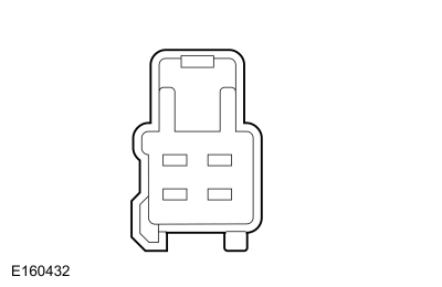 C3167-1, component side DIAGNOSTIC TEST C: RIGHT-HAND (RH) REAR SEAT HEATER INOPERATIVE - WITHOUT HEATED/VENTILATED SEATS
REFER TO the Wiring Diagrams, Cell 119, for schematic and connector information. Normal Operation and Fault SymptomsREFER TO: Second-Row Seats System Operation and Component Description (501-10B Second-Row Seats, Description and Operation). Possible Sources
|
||||||||||||||||
| C1 CHECK THE SEAT HEATER SWITCH INPUT | ||||||||||||||||
Is the resistance less than 3 ohms with the switch pressed and greater than 10,000 ohms with the switch released?
|
||||||||||||||||
| C2 CHECK THE SEAT HEATER SWITCH CIRCUIT FOR OPEN OR SHORT TO GROUND | ||||||||||||||||
Is the resistance between the RHVAC module and the rear seat heater module less than 3 ohms, and greater than 10,000 ohms between the RHVAC module and ground?
|
||||||||||||||||
| C3 CHECK VOLTAGE AT THE SEAT HEATER MODULE | ||||||||||||||||
Is the voltage greater than 11 volts?
|
||||||||||||||||
| C4 CHECK THE HEATER CIRCUITS AND HEATER MATS FOR OPEN | ||||||||||||||||
Is the resistance between 3 and 5 ohms?
|
||||||||||||||||
| C5 CHECK THE HEATER MAT GROUND CIRCUIT FOR OPEN | ||||||||||||||||
Is the resistance less than 3 ohms?
|
||||||||||||||||
| C6 CHECK THE HEATER CIRCUIT FOR OPEN OR SHORT TO GROUND | ||||||||||||||||
Is the resistance less than 3 ohms between the rear seat heater module and the rear seat cushion heater mat, and greater than 10,000 ohms between the rear seat heater module and ground?
|
||||||||||||||||
| C7 CHECK THE CUSHION HEATER FOR OPEN | ||||||||||||||||
Is the resistance between 0.7 and 1.5 ohms?
|
||||||||||||||||
| C8 CHECK FOR OPEN OR SHORT TO GROUND BETWEEN THE HEATER MATS | ||||||||||||||||
Is the resistance less than 3 ohms between the cushion heater mat and the back heater mat, and greater than 10,000 ohms between the cushion heater mat and ground?
|
||||||||||||||||
| C9 CHECK THE TEMPERATURE SENSOR CIRCUIT FOR SHORT TO VOLTAGE | ||||||||||||||||
Is there voltage present?
|
||||||||||||||||
| C10 CHECK THE TEMPERATURE SENSOR CIRCUIT FOR SHORT TO GROUND | ||||||||||||||||
Is the resistance greater than 10000 Ohms?
|
||||||||||||||||
| C11 CHECK THE TEMPERATURE SENSOR AND CIRCUITS FOR OPEN | ||||||||||||||||
Is the resistance between 300 and 300 kOhm?
|
||||||||||||||||
| C12 CHECK THE TEMPERATURE SENSOR FOR OPEN WITH THE HEATER MAT DISCONNECTED | ||||||||||||||||
Is the resistance less than 3 ohms?
|
DIAGNOSTIC TEST D: LEFT-HAND (LH) REAR SEAT HEATER OPERATES CORRECTLY BUT INDICATOR DOES NOT ILLUMINATE WHEN ACTIVATED - WITHOUT HEATED/VENTILATED SEATS REFER TO the Wiring Diagrams, Cell 119, for schematic and connector information. Normal Operation and Fault SymptomsREFER TO: Second-Row Seats System Operation and Component Description (501-10B Second-Row Seats, Description and Operation). Possible Sources
Visual Inspection and Pre-checks
|
|||||||||||||
| D1 CHECK THE SEAT HEATER INDICATOR CIRCUITS FOR SHORT TO GROUND | |||||||||||||
Is the resistance greater than 10000 ohms?
|
|||||||||||||
| D2 CHECK THE SEAT HEATER INDICATOR CIRCUITS FOR OPEN | |||||||||||||
Is the resistance less than 3 ohms?
|
|||||||||||||
| D3 CHECK THE HIGH HEAT INDICATOR | |||||||||||||
Is the high heat indicator on?
|
|||||||||||||
| D4 CHECK THE LOW HEAT INDICATOR | |||||||||||||
Is the low heat indicator on?
|
 DIAGNOSTIC TEST E: RIGHT-HAND (RH) REAR SEAT HEATER OPERATES CORRECTLY BUT INDICATOR DOES NOT ILLUMINATE WHEN ACTIVATED - WITHOUT HEATED/VENTILATED SEATS
REFER TO the Wiring Diagrams, Cell 119, for schematic and connector information. Normal Operation and Fault SymptomsREFER TO: Second-Row Seats System Operation and Component Description (501-10B Second-Row Seats, Description and Operation). Possible Sources
Visual Inspection and Pre-checks
|
|||||||||||||
| E1 CHECK THE SEAT HEATER INDICATOR CIRCUITS FOR SHORT TO GROUND | |||||||||||||
Is the resistance greater than 10000 ohms?
|
|||||||||||||
| E2 CHECK THE SEAT HEATER INDICATOR CIRCUITS FOR OPEN | |||||||||||||
Is the resistance less than 3 ohms?
|
|||||||||||||
| E3 CHECK THE HIGH HEAT INDICATOR | |||||||||||||
Is the high heat indicator on?
|
|||||||||||||
| E4 CHECK THE LOW HEAT INDICATOR | |||||||||||||
Is the low heat indicator on?
|
DIAGNOSTIC TEST F: LEFT-HAND (LH) REAR SEAT HEATER INDICATOR ALWAYS ON - WITHOUT HEATED/VENTILATED SEATS REFER TO the Wiring Diagrams, Cell 119, for schematic and connector information. Normal Operation and Fault SymptomsREFER TO: Second-Row Seats System Operation and Component Description (501-10B Second-Row Seats, Description and Operation). Possible Sources
|
||||
| F1 CHECK THE LEFT REAR SEAT HEATER SWITCH INDICATOR CIRCUIT FOR SHORT TO VOLTAGE | ||||
Is the left rear seat heater indicator still on?
|
DIAGNOSTIC TEST G: RIGHT-HAND (RH) REAR SEAT HEATER INDICATOR ALWAYS ON - WITHOUT HEATED/VENTILATED SEATS REFER TO the Wiring Diagrams, Cell 119, for schematic and connector information. Normal Operation and Fault SymptomsREFER TO: Second-Row Seats System Operation and Component Description (501-10B Second-Row Seats, Description and Operation). Possible Sources
|
||||
| G1 CHECK THE RIGHT REAR SEAT HEATER SWITCH INDICATOR CIRCUIT FOR SHORT TO VOLTAGE | ||||
Is the right rear seat heater indicator still on?
|
DIAGNOSTIC TEST H: BOTH SEAT HEATERS INOPERATIVE - HEATED/VENTILATED SEATS REFER TO the Wiring Diagrams, Cell 119, for schematic and connector information. Normal Operation and Fault SymptomsREFER TO: Second-Row Seats System Operation and Component Description (501-10B Second-Row Seats, Description and Operation). Possible Sources
Visual Inspection and Pre-checks
|
|||||||||||||
| H1 CHECK THE REAR CLIMATE CONTROL (HEATING, VENTILATION AND AIR CONDITIONING) MODULE PARAMETER IDENTIFICATION (PIDS) OF THE SEAT HEATER SWITCH | |||||||||||||
Do the parameter identifications (PIDs) change when the driver and passenger seat heater control switches are pressed and released?
|
|||||||||||||
| H2 CHECK THE SCMF (SECOND ROW CLIMATE CONTROL MODULE) DIAGNOSTIC TROUBLE CODES (DTCS) | |||||||||||||
Are there any SCMF diagnostic trouble codes (DTCs) present?
|
|||||||||||||
| H3 CHECK THE HEATED SEAT POWER SUPPLY CIRCUITS FOR OPEN | |||||||||||||
Is the voltage greater than 11 volts?
|
|||||||||||||
| H4 CHECK THE HEATED SEAT GROUND CIRCUITS FOR OPEN | |||||||||||||
Is the resistance less than 3 ohms?
|
|||||||||||||
| H5 CHECK THE SCMF (SECOND ROW CLIMATE CONTROL MODULE) OPERATION | |||||||||||||
Is the concern still present?
|
DIAGNOSTIC TEST I: LEFT-HAND (LH) SEAT HEATER INOPERATIVE - HEATED/VENTILATED SEATS REFER TO the Wiring Diagrams, Cell 119, for schematic and connector information. Normal Operation and Fault SymptomsREFER TO: Second-Row Seats System Operation and Component Description (501-10B Second-Row Seats, Description and Operation). DTC Fault Trigger Conditions
Possible Sources
|
|||||||||||||||||||||||||||
| I1 CHECK THE RHVAC (REAR HEATING, VENTILATION AND AIR CONDITIONING) MODULE SEAT HEATER CONTROL PID (PARAMETER IDENTIFICATION) | |||||||||||||||||||||||||||
Does the PID change when the left seat heater control switch is pressed and released?
|
|||||||||||||||||||||||||||
| I2 CHECK THE SCMF (REAR SEAT CLIMATE CONTROL MODULE) DIAGNOSTIC TROUBLE CODES (DTCS) | |||||||||||||||||||||||||||
Are there any SCMF diagnostic trouble codes (DTCs) present?
|
|||||||||||||||||||||||||||
| I3 CHECK THE HEATED SEAT POWER SUPPLY CIRCUITS FOR AN OPEN | |||||||||||||||||||||||||||
Is the voltage greater than 11 volts?
|
|||||||||||||||||||||||||||
| I4 CHECK THE HEATED SEAT GROUND CIRCUITS FOR AN OPEN | |||||||||||||||||||||||||||
Is the resistance less than 3 ohms?
|
|||||||||||||||||||||||||||
| I5 CHECK THE HEATING ELEMENT POWER SUPPLY CIRCUIT FOR A SHORT TO VOLTAGE | |||||||||||||||||||||||||||
Is there voltage present?
|
|||||||||||||||||||||||||||
| I6 CHECK THE HEATING ELEMENT POWER SUPPLY CIRCUIT FOR AN OPEN OR A SHORT TO GROUND | |||||||||||||||||||||||||||
Is the resistance between the left seat cushion heating mat and ground greater than 10,000 ohms, and less than 3 ohms between the left seat cushion heating mat and the SCMF?
|
|||||||||||||||||||||||||||
| I7 CHECK THE HEATED SEAT TEMPERATURE SENSOR CIRCUIT FOR AN OPEN OR A SHORT TO GROUND | |||||||||||||||||||||||||||
Is the resistance between the left seat cushion heating mat and ground greater than 10,000 ohms, and less than 3 ohms between the left seat cushion heating mat and the SCMF?
|
|||||||||||||||||||||||||||
| I8 CHECK THE HEATED SEAT TEMPERATURE SENSOR RETURN CIRCUIT FOR AN OPEN OR A SHORT TO GROUND | |||||||||||||||||||||||||||
Is the resistance between the left seat cushion heating mat and ground greater than 10,000 ohms, and less than 3 ohms between the left seat cushion heating mat and the SCMF?
|
|||||||||||||||||||||||||||
| I9 CHECK THE HEATED SEAT TEMPERATURE SENSOR CIRCUIT FOR A SHORT TO VOLTAGE | |||||||||||||||||||||||||||
Is there voltage present?
|
|||||||||||||||||||||||||||
| I10 CHECK THE HEATING ELEMENT GROUND CIRCUIT FOR AN OPEN | |||||||||||||||||||||||||||
Is the resistance less than 3 ohms?
|
|||||||||||||||||||||||||||
| I11 CHECK THE HEATED SEAT MAT FOR AN OPEN OR A SHORT TO GROUND | |||||||||||||||||||||||||||
Is the resistance between 0.6 and 2 Ohms between pins 1 and 4; and greater than 10,000 Ohms between pin 1 and ground?
|
|||||||||||||||||||||||||||
| I12 CHECK THE HEATED SEAT MAT FOR AN OPEN OR A SHORT TO GROUND | |||||||||||||||||||||||||||
Is the resistance between 0.6 and 2 Ohms between pins 1 and 2; and greater than 10,000 Ohms between pin 2 and ground?
|
|||||||||||||||||||||||||||
| I13 CHECK THE CIRCUIT BETWEEN THE SEAT CUSHION HEATING MAT AND THE SEAT BACK HEATING MAT FOR AN OPEN AND A SHORT TO GROUND | |||||||||||||||||||||||||||
Is the resistance between the left seat cushion heating mat and ground greater than 10,000 ohms, and less than 3 ohms between the left seat cushion heating mat and the seat back heating mat?
|
|||||||||||||||||||||||||||
| I14 CHECK THE HEATED SEAT TEMPERATURE SENSOR FOR AN OPEN OR A SHORT TO GROUND | |||||||||||||||||||||||||||
Is the resistance between 300 and 300,000 Ohms between pins 2 and 3; and greater than 10,000 Ohms between pin 2 and ground?
|
|||||||||||||||||||||||||||
| I15 CHECK THE SCMF (REAR SEAT CLIMATE CONTROL MODULE) OPERATION | |||||||||||||||||||||||||||
Is the concern still present?
|
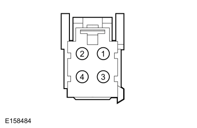 C3167-1, component side
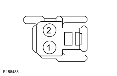 C3372-1, component side DIAGNOSTIC TEST J: RIGHT-HAND (RH) SEAT HEATER INOPERATIVE - HEATED/VENTILATED SEATS
REFER TO the Wiring Diagrams, Cell 119, for schematic and connector information. Normal Operation and Fault SymptomsREFER TO: Second-Row Seats System Operation and Component Description (501-10B Second-Row Seats, Description and Operation). DTC Fault Trigger Conditions
Possible Sources
|
||||||||||||||||||||||||||||||
| J1 CHECK THE RHVAC (REAR HEATING, VENTILATION AND AIR CONDITIONING) MODULE SEAT HEATER CONTROL PID (PARAMETER IDENTIFICATION) | ||||||||||||||||||||||||||||||
Does the PID change when the right seat heater control switch is pressed and released?
|
||||||||||||||||||||||||||||||
| J2 CHECK THE SCMF (REAR CLIMATE CONTROL MODULE) DIAGNOSTIC TROUBLE CODES (DTCS) | ||||||||||||||||||||||||||||||
Are there any SCMF diagnostic trouble codes (DTCs) present?
|
||||||||||||||||||||||||||||||
| J3 CHECK THE SEAT HEATER VOLTAGE SUPPLY CIRCUITS FOR AN OPEN | ||||||||||||||||||||||||||||||
Is the voltage greater than 11 volts?
|
||||||||||||||||||||||||||||||
| J4 CHECK THE SEAT HEATER GROUND CIRCUITS FOR AN OPEN | ||||||||||||||||||||||||||||||
Is the resistance less than 3 ohms?
|
||||||||||||||||||||||||||||||
| J5 CHECK THE HEATER ELEMENT SUPPLY CIRCUIT FOR A SHORT TO VOLTAGE | ||||||||||||||||||||||||||||||
Is there voltage present?
|
||||||||||||||||||||||||||||||
| J6 CHECK THE HEATER ELEMENT SUPPLY CIRCUIT FOR AN OPEN OR A SHORT TO GROUND | ||||||||||||||||||||||||||||||
Is the resistance between the right seat cushion heater mat and ground greater than 10,000 ohms, and less than 3 ohms between the right seat cushion heater mat and the SCMF?
|
||||||||||||||||||||||||||||||
| J7 CHECK THE HEATED SEAT TEMPERATURE SENSOR CIRCUIT FOR AN OPEN OR A SHORT TO GROUND | ||||||||||||||||||||||||||||||
Is the resistance between the right seat cushion heater mat and ground greater than 10,000 ohms, and less than 3 ohms between the right seat cushion heater mat and the SCMF?
|
||||||||||||||||||||||||||||||
| J8 CHECK THE SEAT TEMPERATURE SENSOR RETURN CIRCUIT FOR AN OPEN OR A SHORT TO GROUND | ||||||||||||||||||||||||||||||
Is the resistance between the right seat cushion heater mat and ground greater than 10,000 ohms, and less than 3 ohms between the right seat cushion heater mat and the SCMF?
|
||||||||||||||||||||||||||||||
| J9 CHECK THE HEATED SEAT TEMPERATURE SENSOR CIRCUIT FOR A SHORT TO VOLTAGE | ||||||||||||||||||||||||||||||
Is there voltage present?
|
||||||||||||||||||||||||||||||
| J10 CHECK THE HEATER ELEMENT GROUND CIRCUIT FOR AN OPEN | ||||||||||||||||||||||||||||||
Is the resistance less than 3 ohms?
|
||||||||||||||||||||||||||||||
| J11 CHECK THE HEATED SEAT MAT FOR AN OPEN OR A SHORT TO GROUND | ||||||||||||||||||||||||||||||
Is the resistance between 0.6 and 2 Ohms between pins 1 and 4; and greater than 10,000 Ohms between pin 1 and ground?
|
||||||||||||||||||||||||||||||
| J12 CHECK THE HEATED SEAT MAT FOR AN OPEN OR A SHORT TO GROUND | ||||||||||||||||||||||||||||||
Is the resistance between 0.6 and 2 Ohms between pins 1 and 2; and greater than 10,000 Ohms between pin 2 and ground?
|
||||||||||||||||||||||||||||||
| J13 CHECK THE CIRCUIT BETWEEN THE SEAT CUSHION HEATER MAT AND THE SEAT BACK HEATER MAT FOR AN OPEN AND A SHORT TO GROUND | ||||||||||||||||||||||||||||||
Is the resistance between the right seat cushion heater mat and ground greater than 10,000 ohms, and less than 3 ohms between the right seat cushion heater mat and the seat back heater mat?
|
||||||||||||||||||||||||||||||
| J14 CHECK THE HEATED SEAT TEMPERATURE SENSOR FOR AN OPEN OR A SHORT TO GROUND | ||||||||||||||||||||||||||||||
Is the resistance between 300 and 300,000 Ohms between pins 2 and 3; and greater than 10,000 Ohms between pin 2 and ground?
|
||||||||||||||||||||||||||||||
| J15 CHECK THE SCMF (REAR CLIMATE CONTROL MODULE) OPERATION | ||||||||||||||||||||||||||||||
Is the concern still present?
|
PINPOINT TEST K: BOTH VENTILATED SEATS DO NOT OPERATE REFER TO the Wiring Diagrams, Cell 119, for schematic and connector information. Normal Operation and Fault SymptomsREFER TO: Second-Row Seats System Operation and Component Description (501-10B Second-Row Seats, Description and Operation). Possible Sources
|
||||
| K1 CHECK THE SEAT HEATER OPERATION | ||||
Did the seat heater operate normally?
|
||||
| K2 CHECK THE RHVAC (REAR HEATING, VENTILATION AND AIR CONDITIONING) MODULE SEAT VENTILATION SWITCH PARAMETER IDENTIFICATION (PIDS) | ||||
Do the parameter identifications (PIDs) change when the left and right seat ventilation control switches are pressed and released?
|
||||
| K3 CHECK THE SCMF (REAR CLIMATE CONTROL MODULE) OPERATION | ||||
Is the concern still present?
|
PINPOINT TEST L: LEFT-HAND (LH) VENTILATED SEAT DOES NOT OPERATE/OPERATES INCORRECTLY REFER TO the Wiring Diagrams, Cell 119, for schematic and connector information. Normal Operation and Fault SymptomsREFER TO: Second-Row Seats System Operation and Component Description (501-10B Second-Row Seats, Description and Operation). DTC Fault Trigger Conditions
Possible Sources
|
||||||||||||||||||||||||||||||||||
| L1 CHECK THE LEFT (DRIVER) SEAT HEATER | ||||||||||||||||||||||||||||||||||
Does the left seat heater operate correctly?
|
||||||||||||||||||||||||||||||||||
| L2 CHECK THE RHVAC (REAR HEATING, VENTILATION AND AIR CONDITIONING) MODULE SEAT VENTILATION SWITCH PID (PARAMETER IDENTIFICATION) | ||||||||||||||||||||||||||||||||||
Does the PID change when the left seat ventilation control switch is pressed and released?
|
||||||||||||||||||||||||||||||||||
| L3 CHECK THE FAN MOTOR CIRCUITS FOR A SHORT TO VOLTAGE | ||||||||||||||||||||||||||||||||||
Is there voltage present?
|
||||||||||||||||||||||||||||||||||
| L4 CHECK THE BLOWER MOTOR CIRCUITS FOR A SHORT TO GROUND | ||||||||||||||||||||||||||||||||||
Is the resistance greater than 10000 ohms?
|
||||||||||||||||||||||||||||||||||
| L5 CHECK THE BLOWER MOTOR CIRCUITS FOR AN OPEN | ||||||||||||||||||||||||||||||||||
Is the resistance less than 3 ohms?
|
||||||||||||||||||||||||||||||||||
| L6 CHECK THE BLOWER MOTOR OPERATION | ||||||||||||||||||||||||||||||||||
Is the concern still present?
|
||||||||||||||||||||||||||||||||||
| L7 CHECK THE SCMF (REAR CLIMATE CONTROL MODULE) OPERATION | ||||||||||||||||||||||||||||||||||
Is the concern still present?
|
PINPOINT TEST M: RIGHT-HAND (RH) VENTILATED SEAT DOES NOT OPERATE/OPERATES INCORRECTLY REFER TO the Wiring Diagrams, Cell 119, for schematic and connector information. Normal Operation and Fault SymptomsREFER TO: Second-Row Seats System Operation and Component Description (501-10B Second-Row Seats, Description and Operation). DTC Fault Trigger Conditions
Possible Sources
|
||||||||||||||||||||||||||||||||||
| M1 CHECK THE RIGHT (PASSENGER) HEATED SEAT OPERATION | ||||||||||||||||||||||||||||||||||
Does the right heated seat operate correctly?
|
||||||||||||||||||||||||||||||||||
| M2 CHECK THE RHVAC (HEATED, VENTILATED AND AIR CONDITIONED SEAT) MODULE VENTILATED SEAT SWITCH PID (PARAMETER IDENTIFICATION) | ||||||||||||||||||||||||||||||||||
Does the PID change when the right ventilated seat control switch is pressed and released?
|
||||||||||||||||||||||||||||||||||
| M3 CHECK THE BLOWER MOTOR CIRCUITS FOR A SHORT TO VOLTAGE | ||||||||||||||||||||||||||||||||||
Is there voltage present?
|
||||||||||||||||||||||||||||||||||
| M4 CHECK THE BLOWER MOTOR CIRCUITS FOR A SHORT TO GROUND | ||||||||||||||||||||||||||||||||||
Is the resistance greater than 10000 ohms?
|
||||||||||||||||||||||||||||||||||
| M5 CHECK THE BLOWER MOTOR CIRCUITS FOR AN OPEN | ||||||||||||||||||||||||||||||||||
Is the resistance less than 3 ohms?
|
||||||||||||||||||||||||||||||||||
| M6 CHECK THE BLOWER MOTOR OPERATION | ||||||||||||||||||||||||||||||||||
Is the concern still present?
|
||||||||||||||||||||||||||||||||||
| M7 CHECK THE SCMF (REAR CLIMATE CONTROL MODULE) OPERATION | ||||||||||||||||||||||||||||||||||
Is the concern still present?
|
PINPOINT TEST N: LEFT-HAND (LH) EASY ENTRY POWER SEAT DOES NOT OPERATE For circuit and connector information, refer to Cell 120 in the Wiring Diagrams. Normal Operation and Fault SymptomsREFER TO: Second-Row Seats System Operation and Component Description (501-10B Second-Row Seats, Description and Operation). DTC Fault Trigger Conditions
Possible Sources
|
||||||||||||||||
| N1 CHECK THE DOOR JAMB SWITCH OPERATION | ||||||||||||||||
Did the interior lamp operate correctly?
|
||||||||||||||||
| N2 CHECK THE LEFT (DRIVER) SIDE SECOND ROW SINGLE SEAT EASY ENTRY SEAT FOLD SWITCH OPERATION | ||||||||||||||||
Is the resistance less than 10 ohms with the switch pressed and greater than 10,000 ohms when not pressed?
|
||||||||||||||||
| N3 CHECK THE LEFT (DRIVER) SIDE SECOND ROW SINGLE SEAT EASY ENTRY SEAT FOLD SWITCH CIRCUIT FOR A SHORT TO GROUND | ||||||||||||||||
Is the resistance less than 3 ohms?
|
||||||||||||||||
| N4 CHECK THE LEFT (DRIVER) SIDE SECOND ROW SINGLE SEAT EASY ENTRY SEAT FOLD SWITCH CIRCUIT FOR AN OPEN OR A SHORT TO GROUND | ||||||||||||||||
Is the resistance greater than 10,000 ohms between the left second row seat fold switch and ground, and less than 3 ohms between the left second row seat fold switch and SCMJ?
|
||||||||||||||||
| N5 CHECK THE LEFT (DRIVER) SIDE SECOND ROW EASY ENTRY POWER RELEASE CIRCUIT FOR A GROUND | ||||||||||||||||
Is the resistance less than 3 ohms?
|
||||||||||||||||
| N6 CHECK THE LEFT (DRIVER) SIDE SECOND ROW EASY ENTRY POWER RELEASE ACTUATOR OUTPUT CIRCUIT FOR A SHORT TO VOLTAGE | ||||||||||||||||
Is there voltage present?
|
||||||||||||||||
| N7 CHECK THE LEFT (DRIVER) SIDE SECOND ROW EASY ENTRY POWER RELEASE ACTUATOR OUTPUT CIRCUIT FOR AN OPEN OR A SHORT TO GROUND | ||||||||||||||||
Is the resistance greater than 10,000 ohms between SCMJ and ground, and less than 3 ohms between SCMJ and the left second row Easy Entry actuator?
|
||||||||||||||||
| N8 CHECK LEFT (LH) SECOND ROW EASY ENTRY POWER RELEASE ACTUATOR WITH JUMPER WIRE INSTALLED JUMPER WIRE WITH FUSE | ||||||||||||||||
Did the seat operate correctly with the jumper wire connected?
|
||||||||||||||||
| N9 CHECK LEFT (LH) SECOND ROW EASY ENTRY POWER RELEASE CABLE AND LATCH RELEASE MECHANISM FOR DAMAGE | ||||||||||||||||
Were any problems found with the second row Easy Entry cable and/or the latch mechanism?
|
||||||||||||||||
| N10 CHECK SCMJ (SEAT FOLD ACTUATOR MODULE) OPERATION | ||||||||||||||||
Is the concern still present?
|
PINPOINT TEST O: RIGHT-HAND (RH) EASY ENTRY POWER SEAT DOES NOT OPERATE For circuit and connector information, refer to Cell 120 in the Wiring Diagrams. Normal Operation and Fault SymptomsREFER TO: Second-Row Seats System Operation and Component Description (501-10B Second-Row Seats, Description and Operation). DTC Fault Trigger Conditions
Possible Sources
|
||||||||||||||||
| O1 CHECK DOOR AJAR SWITCH OPERATION | ||||||||||||||||
Did the interior lamp operate correctly?
|
||||||||||||||||
| O2 CHECK RIGHT (RH) SECOND ROW SINGLE SEAT EASY ENTRY SEAT FOLD SWITCH OPERATION | ||||||||||||||||
Is the resistance less than 10 ohms with the switch pressed and greater than 10,000 ohms when not pressed?
|
||||||||||||||||
| O3 CHECK RIGHT (RH) SECOND ROW SINGLE SEAT EASY ENTRY SEAT FOLD SWITCH CIRCUIT GROUND FOR OPEN | ||||||||||||||||
Is the resistance less than 3 ohms?
|
||||||||||||||||
| O4 CHECK RIGHT (RH) SECOND ROW SINGLE SEAT EASY ENTRY SEAT FOLD SWITCH CIRCUIT FOR OPEN OR SHORT TO GROUND | ||||||||||||||||
Is the resistance greater than 10,000 ohms between the right second row single seat fold switch and ground, and less than 3 ohms between the right second row single seat fold switch and SCMJ?
|
||||||||||||||||
| O5 CHECK RIGHT (RH) SECOND ROW EASY ENTRY POWER RELEASE CIRCUIT GROUND FOR OPEN | ||||||||||||||||
Is the resistance less than 3 ohms?
|
||||||||||||||||
| O6 CHECK RIGHT (RH) SECOND ROW EASY ENTRY POWER RELEASE ACTUATOR OUTPUT CIRCUIT FOR SHORT TO VOLTAGE | ||||||||||||||||
Is there voltage present?
|
||||||||||||||||
| O7 CHECK RIGHT (RH) SECOND ROW EASY ENTRY POWER RELEASE ACTUATOR OUTPUT CIRCUIT FOR OPEN OR SHORT TO GROUND | ||||||||||||||||
Is the resistance greater than 10,000 ohms between SCMJ and ground, and less than 3 ohms between SCMJ and the right second row Easy Entry release actuator?
|
||||||||||||||||
| O8 CHECK RIGHT (RH) SECOND ROW EASY ENTRY POWER RELEASE ACTUATOR WITH JUMPER WIRE INSTALLED JUMPER WIRE WITH FUSE | ||||||||||||||||
Did the seat operate correctly with the jumper wire connected?
|
||||||||||||||||
| O9 CHECK RIGHT (RH) SECOND ROW EASY ENTRY POWER RELEASE CABLE AND LATCH RELEASE MECHANISM FOR DAMAGE | ||||||||||||||||
Were any problems found with the second row Easy Entry cable and/or the latch mechanism?
|
||||||||||||||||
| O10 CHECK SCMJ (SEAT FOLD ACTUATOR MODULE) OPERATION | ||||||||||||||||
Is the concern still present?
|
PINPOINT TEST P: DTC: U0140:00 For circuit and connector information, refer to Wiring Diagrams Cell 14. Normal Operation and Fault SymptomsSCMF and BCM communicate via MS-CAN. DTC Fault Trigger Conditions
Possible Sources
|
||||||
| P1 VERIFY CUSTOMER CONCERN | ||||||
Is the observed symptom present?
|
||||||
| P2 CHECK THE NETWORK COMMUNICATION | ||||||
Does the BCM pass the network test?
|
||||||
| P3 RECHECK SCMF (REAR SEAT CLIMATE CONTROL MODULE) DIAGNOSTIC TROUBLE CODES (DTCS) | ||||||
Is DTC U0140:00 still present?
|
||||||
| P4 CHECK FOR DTC U0140:00 IN OTHER MODULES | ||||||
Is DTC U0140:00 set in any other modules?
|
PINPOINT TEST Q: DTC: U0257:00 For circuit and connector information, refer to Wiring Diagrams Cell 14. Normal Operation and Fault SymptomsSCMF and RHVAC module communicate via MS-CAN. DTC Fault Trigger Conditions
Possible Sources
|
||||||
| Q1 VERIFY CUSTOMER CONCERN | ||||||
Is the observed symptom present?
|
||||||
| Q2 CHECK COMMUNICATION NETWORK | ||||||
Does the RHVAC module pass the network test?
|
||||||
| Q3 RECHECK SCMF (REAR SEAT CLIMATE CONTROL MODULE) DIAGNOSTIC TROUBLE CODES (DTCS) | ||||||
Is DTC U0257:00 still present?
|
||||||
| Q4 CHECK FOR DTC U0257:00 IN OTHER MODULES | ||||||
Is DTC U0140:00 set in any other modules?
|
PINPOINT TEST R : DTC: U1000:00 REFER TO the Wiring Diagrams, Cell 119, for schematic and connector information. Normal Operation and Fault SymptomsFirst, CHECK for any other SCMF diagnostic trouble codes (DTCs). CLEAR the diagnostic trouble codes (DTCs). REPEAT the self-test. If DTC U1000:00 returns, INSTALL a new SCMF. REFER TO: Second-Row Seat Climate Control Module (501-10B Second-Row Seats, Removal and Installation). DTC Fault Trigger Conditions
Possible Sources
|
||||||
| No diagnostic actions are available for this symptom or DTC. Refer to: Diagnostic Methods (100-00 General Information, Description and Operation). |
PINPOINT TEST S: DTC: U2100:00 REFER TO the Wiring Diagrams, Cell 119, for schematic and connector information. Normal Operation and Fault SymptomsUsing the diagnostic scan tool, PERFORM a PMI on the SCMF. REPEAT the self-test and CHECK for a successful PMI. CLEAR the diagnostic trouble codes (DTCs). DTC Fault Trigger Conditions
Possible Sources
|
||||||
| No diagnostic actions are available for this symptom or DTC. Refer to: Diagnostic Methods (100-00 General Information, Description and Operation). |
PINPOINT TEST T: DTC: U3000:49 REFER TO the Wiring Diagrams, Cell 119, for schematic and connector information. Normal Operation and Fault SymptomsINSTALL a new SCMF. REFER TO: Second-Row Seat Climate Control Module (501-10B Second-Row Seats, Removal and Installation). DTC Fault Trigger Conditions
Possible Sources
|
||||||
| No diagnostic actions are available for this symptom or DTC. Refer to: Diagnostic Methods (100-00 General Information, Description and Operation). |
Test yourself
A quick Ford Explorer quiz: every answer comes with an explanation and a link to the manual page.