Electronic Function Group
Cruise Control - Diagnosis and Testing
DTC Chart(s):
The diagnosis in this manual assumes a certain level of skill and knowledge of Ford-approved diagnostic procedures.
REFER TO: Diagnostic Methods (100-00 General Information, Description and Operation).
PCM Diagnostic Trouble Code Chart
| Trouble Code |
Description |
Action |
| P0565:01 |
Cruise Control Resume Signal: General Electrical Failure |
GO to Pinpoint Test C |
| P0566:01 |
Cruise Control Cancel Signal: General Electrical Failure |
GO to Pinpoint Test C |
| P0567:01 |
Cruise Control Resume Signal: General Electrical Failure |
GO to Pinpoint Test C |
| P0568:01 |
Cruise Control Set Signal: General Electrical Failure |
GO to Pinpoint Test C |
| P0569:01 |
Cruise Control Coast Signal: General Electrical Failure |
GO to Pinpoint Test C |
| P0579:01 |
Cruise Control Multifunction Input A Circuit Range/Performance: General Electrical Failure |
GO to Pinpoint Test C |
| P0581:13 |
Cruise Control Multifunction Input A High Signal Level: Circuit Open |
GO to Pinpoint Test C |
| P0704:01 |
Clutch Switch Input Circuit: General Electrical Failure |
GO to Pinpoint Test A |
| P1572:01 |
Brake Pedal Switch Circuit: General Electrical Failure |
GO to Pinpoint Test B |
| For all other IPC DTCs |
— |
REFER TO: Instrumentation, Message Center and Warning Chimes (413-01 Instrumentation, Message Center and Warning Chimes, Diagnosis and Testing). |
PCM Diagnostic Trouble Code Chart
| Trouble Code |
Description |
Action |
| P0504:00 |
Brake Switch A/B Correlation: no subtype information |
GO to Pinpoint Test B |
| P0578:00 |
Cruise Control Multifunction Input A Circuit Stuck: No Sub-type Information |
The PCM compares the CAN signal from the different cruise control switch inputs and determines that one or more switches are stuck. DIAGNOSE all other IPC and PCM diagnostic trouble codes (DTCs) first. If no other DTCs are present, CLEAR the DTC. Make sure no cruise control switches are pressed and REPEAT the self-test. If DTC P0578:00 sets again, GO to Pinpoint Test C. |
| P0579:00 |
Cruise Control Multifunction Input A Circuit Range/Performance: No Sub-type Information |
The PCM internally monitors and compares the CAN signal message from the IPC cruise control switch inputs with the PCM internal cruise control state. If the PCM detects a mismatch between the input message and the PCM, DTC P0597:00 is set in the PCM. DIAGNOSE all other IPC and PCM DTCs first. If no other DTCs are present, CLEAR the DTC. REPEAT the self-test. If DTC P0597:00 sets again, GO to Pinpoint Test C. |
| P0833:00 |
Clutch Pedal Switch Circuit "B": No Sub-type Information |
GO to Pinpoint Test E |
| P162D:00 |
Internal Control Module Cruise Control Performance: No Sub Type Information |
The PCM internally monitors the cancel inputs for cruise control. If cruise control cancel is requested and the cruise control output from the PCM is still being monitored, DTC P162D:00 is set in the PCM. DIAGNOSE all other diagnostic trouble codes (DTCs) and symptoms first. GO to Pinpoint Test C. |
| For all other PCM DTCs |
- |
For the procedure, refer to the appropriate Group 303 section. |
Symptom Chart
Symptom Chart:
The diagnosis in this manual assumes a certain level of skill and knowledge of Ford-approved diagnostic procedures.
REFER TO: Diagnostic Methods (100-00 General Information, Description and Operation).
| Condition |
Possible Sources |
Action |
| Module Does Not Respond to Scan Tool |
Refer to Pinpoint Test |
REFER TO: Communication Network (418-00 Communication Network, Diagnosis and Testing). |
| Cruise Control Inoperative |
Refer to Pinpoint Test |
GO to Pinpoint Test A |
| Cruise Control Does Not Cancel When Clutch Pedal Is Depressed |
Refer to Pinpoint Test |
GO to Pinpoint Test D |
| Cruise Control Indicator Lamp Always On/Never On |
Refer to Pinpoint Test |
REFER TO: Instrumentation, Message Center and Warning Chimes (413-01 Instrumentation, Message Center and Warning Chimes, Diagnosis and Testing). |
| Cruise Control Switches Malfunction |
Refer to Pinpoint Test |
GO to Pinpoint Test C |
| Cruise Control Cannot Set Speed Above 105 km/h, 113 km/h, 121 km/h or 129 km/h |
The MyKey® Restricted Driver key is in use and the MyKey® maximum speed restriction is enabled. |
CHECK whether a MyKey® Limited Access Key is being used. With the Admin Key, CHECK whether the MyKey® Speed Limiter is turned on. REFER to the Owner's Literature. If necessary, CHECK cruise control operation with the Admin Key. |
Pinpoint Tests
P0704:01 Cruise Control Inoperative
For circuit diagrams and connector information, REFER TO: Cell 31 of the Electrical Circuit Diagrams.
Normal Operation and Fault Symptoms
The cruise control function is controlled by the brake pedal switch, which is hard-wired to the PCM through the signal and return circuit, and the cruise control cancel switch, which is hard-wired to the PCM. There are 5 cruise control switches, each with a special function that uses a different resistance value. The PCM supplies a reference voltage to the cruise control switches and monitors the voltage drop when a cruise control switch is pressed. The voltage drop depends on the resistance of each switch, providing a specific indication to the IPC of which switch is pressed.
The brake switch is an input to the PCM for cruise control operation. When the brake pedal is depressed, the normally open brake switch closes and applies a voltage signal to the PCM to deactivate cruise control, if it is on. The cruise control cancel switch is a normally closed switch that applies a ground signal to the IPC. When the brake pedal is depressed, the switch opens and removes the ground signal to the PCM.
The IPC sends a network message over HS-CAN to the PCM. This is a redundant signal to the PCM. The PCM monitors both signals and compares the inputs to confirm the correct sequence of brake input signals is received.
DTC Fault Trigger Conditions
| Trouble Code |
Description |
Fault Trigger Conditions |
| P0704:01 |
Clutch Switch Input Circuit: General Electrical Failure |
Sets when the IPC detects a short to ground in the clutch pedal cruise control deactivation switch signal during the self-test. |
Possible Sources
- Wiring, Terminals or Connectors
- Clockspring
- TP sensor
- Cruise control switch
- Cruise Control Deactivation Switch
- Clutch Pedal Cruise Control Deactivation Switch (Manual Transmission)
- PCM
- PCM
- ABS Module
PINPOINT TEST A: P0704:01 CRUISE CONTROL INOPERATIVE
| A1 CHECK THE DIAGNOSTIC TROUBLE CODES (DTCS) |
- Review the DTCs recorded from the IPC and PCM self-tests.
Are any diagnostic trouble codes recorded?
| Yes |
For DTC P0704:01, GO to A5. For all other DTCs, REFER to the DTC Charts in this section. |
|
| A2 CHECK ABS (ANTI-LOCK BRAKE SYSTEM) MODULE DTCS |
- Review the DTCs recorded from the ABS module self-test.
Are any ABS DTCs recorded?
| Yes |
REFER TO: Anti-Lock Brake System (ABS) and Stability Control System (206-09 Anti-Lock Brake System (ABS) and Stability Control System, Diagnosis and Testing). |
|
| A3 MONITOR THE BRAKE PEDAL PARAMETER IDENTIFICATION (PID) |
- Using the diagnostic scan tool, view the PCM PIDs.
- Using the table, monitor BOO1 and BOO2 while depressing and releasing the brake pedal.
| Brake pedal position | BOO1 PID | BOO2 PID |
| Released |
Off |
Off |
| Applied |
On |
On |
Do the PID values match the brake pedal position?
| Yes |
For an automatic transmission, GO to A4.
For a manual transmission, GO to A5. |
|
| A4 MONITOR THE PCM TRANSGEAR PARAMETER IDENTIFICATION (PID) |
- Using the diagnostic scan tool, view the PCM PIDs.
- Monitor the PCM TRANSGEAR PID.
Does the PID value match the TRANSGEAR selector lever position?
| No |
REFER to: External Controls (307-05 External Automatic Transmission). Controls - 6-Speed PowerShift Transmission - DPS6/6DCT250, Diagnosis and Testing. |
|
| A5 CHECK THE CLUTCH PEDAL CRUISE CONTROL DEACTIVATION SWITCH PARAMETER IDENTIFICATION (PID) |
- Using the diagnostic scan tool, view the PCM PIDs.
- Monitor the PCM CPP_TOP PID while depressing and releasing the clutch pedal.
Does the PID display YES with the clutch pedal depressed and NO with the clutch pedal released?
| No |
If the CPP_TOP value always reads YES (depressed), GO to A7.
If the CPP_TOP value always reads NO (released), GO to Pinpoint Test D. |
|
| A6 CHECK THE CRUISE CONTROL SWITCH PIDS |
- Using a diagnostic scan tool, monitor the IPC PIDs.
- Press each cruise control switch while monitoring the cruise control switch PIDs, as specified in the table below.
| Cruise Control Switch |
CRUISE_SW PID Values |
| — |
NO Pressed |
| RES/CANCEL |
CANCEL/RESUME |
| ON |
ON |
| OFF |
OFF |
| SET + |
SET+ |
| SET - |
SET- |
Do the PID values match the switch position?
| No |
If only one switch does not show the correct PID value, INSTALL a new cruise control switch.
REFER to: Multifunction Switch on Steering Wheel (211-05 Steering Wheel and Column Electrical Components, Removal and Installation).
Otherwise, GO to Pinpoint Test C. |
|
| A7 CHECK THE CLUTCH PEDAL FUNCTIONAL SWITCH PARAMETER IDENTIFICATION (PID) WITH THE CLUTCH PEDAL CRUISE CONTROL DEACTIVATION SWITCH DISCONNECTED |
- Disconnect the clutch pedal cruise control deactivation switch C2354.
- Using the diagnostic scan tool, view the PCM PIDs.
- Monitor the PCM CPP_TOP PID.
Does the PID value read NO?
| Yes |
INSTALL a new clutch pedal cruise control deactivation switch. |
| No |
REPAIR the circuit for a short to ground. |
|
| A8 CHECK THE PCM (POWERTRAIN CONTROL MODULE) OPERATION |
- Disconnect all PCM connectors.
- Repair:
- corrosion (install new connector or terminals - clean module pins)
- damaged or bent pins - install new terminals/pins
- backed-out pins - install new pins as necessary
- Connect the PCM connectors. Make sure they are fully seated and locked.
- Reconnect all previously disconnected connectors. Make sure they are installed and locked correctly.
- Operate the system and determine if the concern is still present.
Is the concern still present?
| Yes |
CHECK OASIS for any applicable Technical Service Bulletins (TSBs). If a TSB exists for this concern, STOP this test and FOLLOW the TSB instructions. If no TSBs apply to this concern,
 Click here to access the guided routine (PCM). |
| No |
The system is currently operating correctly. The concern may have been caused by a loose or corroded connector. |
|
P0504:00 or P1572:01
For circuit diagrams and connector information, REFER TO: Cell 31 of the Electrical Circuit Diagrams.
Normal Operation and Failure Conditions
The brake pedal switch and cruise control deactivation switch signals are inputs to the PCM and IPC respectively for cruise control operation. When the brake pedal is applied, the normally open brake pedal switch closes and supplies a voltage signal to the PCM to disengage cruise control, if engaged. The cruise control deactivation switch is a normally closed switch that provides a ground signal to the IPC. When the brake pedal is depressed, the switch opens and removes the ground signal from the IPC. The IPC sends a network message over the HS-CAN bus to the PCM. This is a redundant signal for the PCM. The PCM receives both signals and compares the inputs to confirm that the correct brake input sequence is received.
DTC Fault Trigger Conditions
| Trouble Code |
Description |
Fault Trigger Conditions |
| P0504:00 |
Brake Switch A/B Correlation: no subtype information |
Sets when the PCM does not detect the correct brake pedal input signal sequence from both the cruise control deactivation switch and the brake pedal switches when the brake pedal is depressed and released. |
| P1572:01 |
Brake Pedal Switch Circuit: General Electrical Failure |
Sets when the IPC detects an open circuit in the cruise control deactivation switch signal during the self-test. |
Possible Sources
- Wiring, Terminals or Connectors
- Stop Lamp Switch
- Cruise Control Deactivation Switch
- PCM
- PCM
- RFA
PINPOINT TEST B: P0504:00 OR P1572:01
| B1 CHECK STOP LAMP OPERATION |
Do the brake lights operate correctly?
| No |
Refer to: Stop Lamps (417-01 Exterior Lighting, Diagnosis and Testing). |
|
| B2 MONITOR THE BRAKE PEDAL PARAMETER IDENTIFICATION (PID) |
- Using the diagnostic scan tool, view the PCM PIDs.
- Using the table, monitor BOO1 and BOO2 while depressing and releasing the brake pedal.
| Brake pedal position | BOO1 PID | BOO2 PID |
| Released |
Off |
Off |
| Applied |
On |
On |
Do the PID values match the brake pedal position?
| Yes |
For DTC P0504:00, GO to B11.
For DTC P1572:01, GO to B10. |
| No |
If the BOO1 PID value is incorrect, GO to B3. If the BOO2 PID value always reads OFF, GO to B4. If the BOO2 PID value always reads ON, GO to B7. |
|
| B3 CHECK BRAKE SWITCH CIRCUIT |
- Disconnect PCM C1381B 1 L GTDI.
- Disconnect the PCM C175B 1.6 L TiVCT.
- Disconnect the PCM C1915B 1.6L GTDI.
- While depressing and releasing the brake pedal, measure:
1 L GTDI
| Positive lead | Measurement/Action | Negative lead |
| C1381B-66 |
 |
Ground |
1.6 L TiVCT
| Positive lead | Measurement/Action | Negative lead |
| C175B-2 |
|
Ground |
1.6 L GTDI
| Positive lead | Measurement/Action | Negative lead |
| C1915B-66 |
|
Ground |
Is the voltage greater than 11 V with the brake pedal depressed and 0 V with the brake pedal released?
|
| B4 MONITOR THE CRUISE CONTROL DEACTIVATION SWITCH PID |
- Disconnect the cruise control deactivation switch C278.
- Using the diagnostic scan tool, view the PCM PIDs.
- Monitor the PCM BOO2 PID.
Does the PID read ON?
| Yes |
INSTALL a new cruise control deactivation switch.
REFER to: Cruise Control Deactivation Switch (419-03 Cruise Control, Removal and Installation). |
| No |
If equipped with a Keyless Entry/Push Button Start system, GO to B5. Otherwise, GO to B6. |
|
| B5 CHECK THE RFA (REMOTE FUNCTION ACTUATOR) MODULE FOR A SHORT TO GROUND |
- Disconnect the RFA module C3503B.
- Using the diagnostic scan tool, view the PCM PIDs.
- Monitor the PCM BOO2 PID.
Does the BOO2 PID read ON?
| Yes |
INSTALL a new RFA module.
REFER to: Remote Function Actuator (RFA) Module (419-10 Multifunction Electronic Modules, Removal and Installation). |
|
| B6 CHECK THE CRUISE CONTROL DEACTIVATION SWITCH SIGNAL CIRCUIT FOR A SHORT TO GROUND |
- Disconnect the IPC C220A.
- Action:
| Positive lead | Measurement/Action | Negative lead |
| C278-2 |
 |
Ground |
Is the resistance greater than 10000 Ohms?
|
| B7 CHECK THE CRUISE CONTROL DEACTIVATION SWITCH FOR AN OPEN CIRCUIT |
- Disconnect the cruise control deactivation switch C278.
- Using the diagnostic scan tool, view the PCM PIDs.
- Monitor the PCM BOO2 PID.
- Connect the fused jumper:
| Positive lead | Measurement/Action | Negative lead |
| C278-2 |
 |
C278-1 |
Does the BOO2 PID read OFF?
| Yes |
REMOVE the fusible link. INSTALL a new cruise control deactivation switch.
REFER to: Cruise Control Deactivation Switch (419-03 Cruise Control, Removal and Installation). |
| No |
REMOVE the fusible link. GO to B8. |
|
| B8 CHECK THE CRUISE CONTROL DEACTIVATION SWITCH GROUND CIRCUIT FOR AN OPEN CIRCUIT |
- Action:
| Positive lead | Measurement/Action | Negative lead |
| C278-1 |
|
Ground |
Is the resistance less than 3 ohms?
|
| B9 CHECK THE CRUISE CONTROL DEACTIVATION SWITCH INPUT TO THE IPC (INSTRUMENT PANEL CLUSTER) FOR AN OPEN CIRCUIT |
- Disconnect the IPC C220A.
- Action:
| Positive lead | Measurement/Action | Negative lead |
| C278-2 |
|
C220A-29 |
Is the resistance less than 1 Ohm?
|
| B10 CHECK THE IPC (INSTRUMENT PANEL CLUSTER) FOR PROPER OPERATION |
- Disconnect all IPC connectors.
- Repair:
- corrosion (install new connector or terminals - clean module pins)
- damaged or bent pins - install new terminals/pins
- backed-out pins - install new pins as necessary
- Connect the IPC connectors. Make sure they are fully seated and locked.
- Reconnect all previously disconnected connectors. Make sure they are installed and locked correctly.
- Operate the system and determine if the concern is still present.
Is the concern still present?
| Yes |
CHECK OASIS for any applicable Technical Service Bulletins (TSB). If a TSB exists for this concern, STOP this test and FOLLOW the TSB instructions. If no TSB applies to this concern, INSTALL a new IPC.
REFER to: Instrument Cluster (IPC) (413-01 Instrument Cluster, Message Center and Warning Chimes, Removal and Installation). |
| No |
The system is currently operating correctly. The concern may have been caused by a loose or corroded connector. |
|
| B11 CHECK PCM (POWERTRAIN CONTROL MODULE) OPERATION |
- Disconnect all PCM connectors.
- Repair:
- corrosion (install new connector or terminals - clean module pins)
- damaged or bent pins - install new terminals/pins
- backed-out pins - install new pins as necessary
- Connect the PCM connectors. Make sure they are fully seated and locked.
- Connect all previously disconnected connectors.
- Operate the system and determine if the concern is still present.
Is the concern still present?
| Yes |
CHECK OASIS for any applicable Technical Service Bulletins (TSBs). If a TSB exists for this concern, STOP this test and FOLLOW the TSB instructions. If no TSBs apply to this concern,
Click here to access the guided routine (PCM). |
| No |
The system is currently operating correctly. The concern may have been caused by a loose or corroded connector. |
|
Cruise Control Switches Malfunction
For circuit diagrams and connector information, REFER TO: Cell 31 of the Electrical Circuit Diagrams.
Normal Operation and Fault Symptoms
There are 5 cruise control switches, each of which is a special function that uses different resistance values. The PCM supplies a reference voltage to the cruise control switches and monitors the voltage drop when a cruise control switch is pressed. The voltage drop depends on the resistance of each switch, providing the IPC with a specific indication of which switch is pressed. The IPC sends a network message over HS-CAN to the PCM, activating and controlling the cruise control system.
DTC Fault Trigger Conditions
| Trouble Code |
Description |
Fault Trigger Conditions |
| P0565:01 |
Cruise Control Resume Signal: General Electrical Failure |
Continuous on-demand DTC that sets after 1 minute if the IPC detects that the ON switch is pressed and held or stuck. |
| P0566:01 |
Cruise Control Cancel Signal: General Electrical Failure |
Continuous on-demand DTC that sets after 1 minute if the IPC detects that the OFF switch is pressed and held or stuck. |
| P0567:01 |
Cruise Control Resume Signal: General Electrical Failure |
Continuous on-demand DTC that sets after 1 minute if the IPC detects that the CAN/RES switch is pressed and held or stuck. |
| P0568:01 |
Cruise Control Set Signal: General Electrical Failure |
Continuous on-demand DTC that sets after 1 minute if the IPC detects that the SET+ switch is pressed and held or stuck. |
| P0569:01 |
Cruise Control Coast Signal: General Electrical Failure |
Continuous on-demand DTC that sets after 1 minute if the IPC detects that the SET switch is pressed and held or stuck. |
| P0578:00 |
Cruise Control Multifunction Input A Circuit Stuck: No Sub-type Information |
Continuous on-demand DTC that sets if the IPC detects that the cruise control switch input is in an unknown state for more than 1 second. |
| P0579:00 |
Cruise Control Multifunction Input A Circuit Range/Performance: No Sub-type Information |
Continuous on-demand DTC that sets if the IPC detects that the cruise control switch input is in an unknown state for more than 1 second. |
| P0579:01 |
Cruise Control Multifunction Input A Circuit Range/Performance: General Electrical Failure |
Continuous on-demand DTC that sets if the IPC detects that the cruise control switch input is in an unknown state for more than 1 second. |
| P0581:13 |
Cruise Control Multifunction Input A High Signal Level: Circuit Open |
Continuous on-demand DTC that sets after 1 minute if the IPC detects an open circuit in the cruise control switch circuits. |
| P162D:00 |
Internal Control Module Cruise Control Performance: No Sub Type Information |
Continuous on-demand DTC that sets after 1 minute if the IPC detects that the ON switch is pressed and held or stuck. |
Possible Sources
- Wiring, Terminals or Connectors
- Clockspring
- Cruise control switch
- PCM
- PCM
PINPOINT TEST C: CRUISE CONTROL SWITCHES MALFUNCTION
| C1 PERFORM NETWORK TEST |
- Using a scan tool, perform the network test.
Do the PCM and IPC pass the network test?
| No |
REFER TO: Communication Network (418-00 Communication Network, Diagnosis and Testing). |
|
| C2 CHECK CRUISE CONTROL SWITCH PID |
- Using a scan tool, view the PCM parameter identifications (PIDs).
- Press each cruise control switch while monitoring the CRUISE_SW PID.
| Cruise Control Switch |
CRUISE_SW PID Values |
| — |
NO Pressed |
| RES/CANCEL |
CANCEL/RESUME |
| ON |
ON |
| OFF |
OFF |
| SET + |
SET+ |
| SET - |
SET- |
Do the PID values match the switch position?
| No |
If only one switch does not show the correct PID value, INSTALL a new cruise control switch.
REFER to: Multifunction Switch on Steering Wheel (211-05 Steering Wheel and Column Electrical Components, Removal and Installation).
Otherwise, GO to C3. |
|
| C3 CHECK CRUISE CONTROL SWITCH CIRCUIT FOR SHORT TO VOLTAGE |
- Disconnect the IPC C220A.
- Turn on the parking lamps.
- Action:
| Positive lead | Measurement/Action | Negative lead |
| C220A-28 |
|
Ground |
| C220A-27 |
|
Ground |
Is there voltage present?
| Yes |
TURN OFF the parking lamps. GO to C4. |
| No |
TURN OFF the parking lamps. GO to C7. |
|
| C4 CHECK CRUISE CONTROL SWITCH CIRCUIT FOR SHORT TO VOLTAGE WITH CLOCKSPRING DISCONNECTED |
- Disconnect the clockspring C218B.
- Turn on the parking lamps.
- Action:
| Positive lead | Measurement/Action | Negative lead |
| C220A-28 |
|
Ground |
| C220A-27 |
|
Ground |
Is there voltage present?
| No |
TURN OFF the parking lamps. GO to C5. |
|
| C5 CHECK CLOCKSPRING FOR SHORT TO VOLTAGE |
- Connect the clockspring C218B.
 WARNING: Make sure no one is in the vehicle and nothing blocks or is placed in front of any airbag module when the battery is connected. Failure to follow these instructions may result in serious injury in the event of accidental deployment.
- Remove the driver air bag.
REFER to: Driver Air Bag (501-20B Supplemental Restraint System, Removal and Installation).
- Disconnect the clockspring C218C.
- Turn on the parking lamps.
- Action:
| Positive lead | Measurement/Action | Negative lead |
| C220A-28 |
|
Ground |
| C220A-27 |
|
Ground |
Is there voltage present?
| Yes |
INSTALL a new clock spring.
Refer to: Clock Spring (501-20B Supplemental Restraint System, Removal and Installation). |
|
| C6 CHECK CRUISE CONTROL SWITCH CIRCUIT FOR SHORT TO LAMP CIRCUIT |
- Disconnect the cruise control switch C2999.
- Action:
| Positive lead | Measurement/Action | Negative lead |
| C2999-2 |
|
C2999-3 |
| C2999-4 |
|
C2999-3 |
Is the resistance greater than 10000 ohms?
| Yes |
INSTALL a new cruise control switch.
REFER to: Steering Wheel Multifunction Switch (211-05 Steering Wheel and Column Electrical Components, Removal and Installation). |
| No |
REPAIR the steering wheel wiring harness or INSTALL a new steering wheel.
REFER to: Steering Wheel (211-04 Steering Column, Removal and Installation). |
|
| C7 CHECK CRUISE CONTROL SWITCH CIRCUIT FOR SHORT TO GROUND |
- Remove the driver air bag.
REFER to: Driver Air Bag (501-20B Supplemental Restraint System, Removal and Installation).
- Disconnect the cruise control switch C2999.
- Action:
| Positive lead | Measurement/Action | Negative lead |
| C220A-28 |
|
Ground |
| C220A-27 |
|
Ground |
Is the resistance greater than 10000 ohms?
|
| C8 CHECK CLOCKSPRING FOR SHORT TO GROUND |
- Disconnect the clockspring C218B.
- Action:
| Positive lead | Measurement/Action | Negative lead |
| C220A-28 |
|
Ground |
| C220A-27 |
|
Ground |
Is the resistance greater than 10000 ohms?
|
| C9 CHECK STEERING WHEEL WIRING HARNESS FOR SHORT TO GROUND |
- Connect the clockspring C218B.
- Disconnect the clockspring C218C.
- Action:
| Positive lead | Measurement/Action | Negative lead |
| C220A-28 |
|
Ground |
| C220A-27 |
|
Ground |
Is the resistance greater than 10000 ohms?
| Yes |
REPAIR the steering wheel wiring harness or INSTALL a new steering wheel.
REFER to: Steering Wheel (211-04 Steering Column, Removal and Installation). |
| No |
INSTALL a new clock spring.
Refer to: Clock Spring (501-20B Supplemental Restraint System, Removal and Installation). |
|
| C10 CHECK CRUISE CONTROL SWITCH CIRCUIT FOR OPEN |
- Disconnect the clockspring C218B.
- Action:
| Positive lead | Measurement/Action | Negative lead |
| C220A-28 |
|
C218B-9 |
| C220A-27 |
|
C218B-10 |
Is the resistance less than 3 ohms?
| No |
REPAIR the faulty circuit. |
|
| C11 CHECK CLOCKSPRING FOR OPEN |
- Disconnect the clockspring C218C.
- Action:
| Positive lead | Measurement/Action | Negative lead |
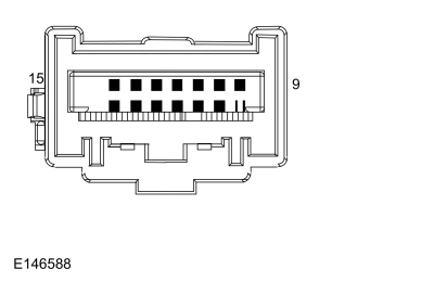 C218C pin 8, component side |
|
 C218B pin 9, component side |
| Positive lead | Measurement/Action | Negative lead |
| C218C pin 9, component side |
|
C218B pin 10, component side |
Is the resistance less than 3 ohms?
| No |
INSTALL a new clock spring.
Refer to: Clock Spring (501-20B Supplemental Restraint System, Removal and Installation). |
|
| C12 CHECK STEERING WHEEL WIRING HARNESS FOR OPEN |
- Action:
| Positive lead | Measurement/Action | Negative lead |
| C218C-9 |
|
C2999-2 |
| C218C-8 |
|
C2999-4 |
Is the resistance less than 1 Ohm?
| Yes |
INSTALL a new cruise control switch.
REFER to: Steering Wheel Multifunction Switch (211-05 Steering Wheel and Column Electrical Components, Removal and Installation). |
| No |
REPAIR the steering wheel wiring harness or INSTALL a new steering wheel.
REFER to: Steering Wheel (211-04 Steering Column, Removal and Installation). |
|
| C13 CHECK IPC (INSTRUMENT PANEL CLUSTER) OPERATION |
- Disconnect all IPC connectors.
- Repair:
- corrosion (install new connector or terminals - clean module pins)
- damaged or bent pins - install new terminals/pins
- backed-out pins - install new pins as necessary
- Connect the IPC connectors. Make sure they are fully seated and locked.
- Reconnect all previously disconnected connectors. Make sure they are installed and locked correctly.
- Operate the system and determine if the concern is still present.
Is the concern still present?
| Yes |
CHECK OASIS for any applicable Technical Service Bulletins (TSB). If a TSB exists for this concern, STOP this test and FOLLOW the TSB instructions. If no TSB applies to this concern, INSTALL a new IPC.
REFER to: Instrument Cluster (IPC) (413-01 Instrument Cluster, Message Center and Warning Chimes, Removal and Installation). |
| No |
The system is currently operating correctly. The concern may have been caused by a loose or corroded connector. |
|
Cruise Control Does Not Cancel When Clutch Pedal Is Depressed
For circuit diagrams and connector information, REFER TO: Cell 31 of the Electrical Circuit Diagrams.
Normal Operation and Fault Symptoms
Vehicles equipped with a manual transmission have an additional clutch pedal cruise control deactivator switch. The clutch pedal cruise control deactivator switch (upper travel) is a normally open switch with the clutch pedal released. When the clutch pedal is depressed, the clutch pedal cruise control deactivator switch moves to the closed position, which sends a ground signal to the IPC. The IPC sends a network message over the HS-CAN bus to the PCM, which disables the cruise control system.
Possible Sources
- Wiring, Terminals and Connectors
- Clutch Pedal Cruise Control Deactivator Switch
- PCM
- PCM
PINPOINT TEST D: CRUISE CONTROL DOES NOT CANCEL WHEN CLUTCH PEDAL IS DEPRESSED
| D1 CHECK CLUTCH PEDAL CRUISE CONTROL DEACTIVATOR SWITCH (CPP_TOP) PID (PARAMETER IDENTIFICATION) |
- Using a scan tool, view the PCM parameter identifications (PIDs).
- Monitor the PCM CPP_TOP PID while depressing and releasing the clutch pedal.
Does the PID display YES with the clutch pedal depressed and NO with the clutch pedal released?
|
| D2 CHECK CLUTCH PEDAL CRUISE CONTROL DEACTIVATOR SWITCH |
- Disconnect: Clutch Pedal Cruise Control Deactivator Switch C2354
- Connect a fused jumper wire:
Click to display connectors
| Positive lead | Measurement/Action | Negative lead |
| C2354-2 |
|
C2354-3 |
- Monitor the PCM CPP_TOP PID.
Does the PID value display as YES?
| Yes |
REMOVE the fused jumper. INSTALL a new clutch pedal cruise control deactivator switch. |
| No |
REMOVE the fused jumper. GO to D3. |
|
| D3 CHECK CLUTCH PEDAL DEACTIVATOR GROUND CIRCUIT FOR OPEN |
- Connect a fused jumper wire:
Click to display connectors
| Positive lead | Measurement/Action | Negative lead |
| C2354-3 |
|
Ground |
- Monitor the PCM CPP_TOP PID.
Does the PID value display as YES?
| Yes |
REMOVE the fused jumper. REPAIR the ground circuit. |
| No |
REMOVE the fuse jumper. GO to D4. |
|
| D4 CHECK CLUTCH PEDAL CRUISE CONTROL DEACTIVATOR SWITCH SIGNAL CIRCUIT FOR OPEN |
- Action:
Click to display the connectors
| Positive lead | Measurement/Action | Negative lead |
| C2354-2 |
|
C220A-10 |
Is the resistance less than 1 Ohm?
|
| D5 CHECK IPC (INSTRUMENT PANEL CLUSTER) OPERATION |
- Disconnect and inspect all IPC connectors.
- Repair:
- corrosion (install new connector or terminals - clean module pins)
- damaged or bent terminals/pins - install new terminals/pins
- pushed-out pins - install new pins as necessary
- Connect the IPC connectors. Make sure they are fully seated and locked.
- Operate the system and determine if the concern is still present.
Is the concern still present?
| Yes |
CHECK OASIS for any applicable Technical Service Bulletins (TSB). If a TSB exists for this concern, STOP this test and FOLLOW the TSB instructions. If no TSB applies to this concern, INSTALL a new IPC.
REFER to: Instrument Cluster (IPC) (413-01 Instrument Cluster, Message Center and Warning Chimes, Removal and Installation). |
| No |
The system is currently operating correctly. The concern may have been caused by module connections. ADDRESS the root cause of any connector or terminal issues. |
|
| D6 CHECK THE PCM (POWERTRAIN CONTROL MODULE) FOR PROPER OPERATION |
- Disconnect and inspect all PCM connectors.
- Repair:
- corrosion (install new connector or terminals - clean module pins)
- damaged or bent terminals/pins - install new terminals/pins
- pushed-out pins - install new pins as necessary
- Connect the PCM connectors. Make sure they are fully seated and locked.
- Operate the system and determine if the concern is still present.
Is the concern still present?
| Yes |
CHECK OASIS for any applicable Technical Service Bulletins (TSBs). If a TSB exists for this concern, STOP this test and FOLLOW the TSB instructions. If no TSBs apply to this concern,
Click here to access the guided routine (PCM). |
| No |
The system is currently operating correctly. The concern may have been caused by module connections. ADDRESS the root cause of any connector or terminal issues. |
|
P0833:00
Normal Operation and Fault Symptoms
Vehicles equipped with a manual transmission have an additional clutch pedal cruise control deactivation switch. The clutch pedal cruise control deactivation switch is a normally open switch actuated by the clutch pedal. When the clutch pedal is depressed, the clutch pedal travel moves the deactivation switch to the closed position, which provides a ground signal to the IPC. The IPC sends a network message over HS-CAN to the PCM, deactivating the cruise control system.
DTC Fault Trigger Conditions
| Trouble Code |
Description |
Fault Trigger Conditions |
| P0833:00 |
Clutch Pedal Position Switch Circuit B: No Sub-type Information |
This is a logic fault code that sets when the PCM receives a vehicle speed input indicating vehicle movement and does not detect a switch input from the CPP switch or the clutch pedal cruise control deactivation switch. This condition disables cruise control. |
Possible Sources
- Wiring, Terminals and Connectors
- PCM
PINPOINT TEST E: P0833:00
| E1 CHECK THE CLUTCH PEDAL POSITION (CPP) PARAMETER IDENTIFICATION (PIDS) |
- Using a scan tool, view the PCM parameter identifications (PIDs).
- Monitor the PCM PIDs CPP_TOP and CPP_BOT while depressing and releasing the clutch pedal.
Does the CPP_TOP PID display YES with the clutch pedal depressed and NO with the clutch pedal released?
| No |
If the CPP_TOP PID always displays YES (applied), CHECK the CPP switch. Refer to the appropriate Group 303 procedure.
If the CPP_TOP PID always displays NO (released), GO to Pinpoint Test D. |
|
| E2 CHECK PCM (POWERTRAIN CONTROL MODULE) OPERATION |
- Disconnect and inspect all PCM connectors.
- Repair:
- corrosion (install new connector or terminals - clean module pins)
- damaged or bent terminals/pins - install new terminals/pins
- pushed-out pins - install new pins as necessary
- Connect the PCM connectors. Make sure they are fully seated and locked.
- Operate the system and determine if the concern is still present.
Is the concern still present?
| Yes |
CHECK OASIS for any applicable Technical Service Bulletins (TSBs). If a TSB exists for this concern, STOP this test and FOLLOW the TSB instructions. If no TSBs apply to this concern,
Click here to access the guided routine (PCM). |
| No |
The system is currently operating correctly. The concern may have been caused by module connections. ADDRESS the root cause of any connector or terminal issues. |
|