Electrical

Horn - Diagnosis and Testing

~12min read
1special tools

Diagnostic Trouble Code Chart

The diagnosis in this manual assumes a certain level of skill and knowledge of Ford-approved diagnostic procedures.
REFER TO: Diagnostic Methods (100-00 General Information, Description and Operation).


DTC Chart


Trouble Code Description Action
B1323:11 Horn Switch: Short to Ground GO to Pinpoint Test B
B1C55:12 Horn Relay: Short to Battery GO to Pinpoint Test A
B1C55:14 Horn Relay: Short to Ground or Open
  • If the horn does not operate, GO to Location Test A.
  • If the horn is always on, GO to Location Test B.

Symptom Chart

Horn Symptom Chart

The diagnosis in this manual assumes a certain level of skill and knowledge of Ford-approved diagnostic procedures.
REFER TO: Diagnostic Methods (100-00 General Information, Description and Operation).


Symptom Chart


Condition Possible Sources Action
Horn does not sound
  • Refer to Diagnostic Test
  • GO to Pinpoint Test A
Horn is always on
  • Refer to Diagnostic Test
  • GO to Pinpoint Test B

Pinpoint Tests


Ford Fusion. Horn. Diagnosis and Testing Ford Fusion. Horn. Diagnosis and Testing DIAGNOSTIC TEST A: HORN INOPERATIVE

For circuit and connector information, refer to Cell 44 of the Wiring Diagrams.

Normal Operation and Fault Symptoms

REFER TO: Horn (413-06 Horn).

DTC Fault Trigger Conditions

Trouble Code Description Fault Trigger Condition
BCM B1C55:12 Horn Relay: Short to Battery Sets when the BCM detects a short to voltage in the horn relay control circuit.
BCM B1C55:14 Horn Relay: Short to Ground or Open Sets when the BCM detects an open in the horn relay control circuit.

Possible Sources

  • Fuse
  • Wiring, Terminals or Connectors
  • Clockspring
  • Horn
  • Horn Relay
  • BJB
  • Steering Wheel
  • Driver Airbag (Horn Switch)
  • BCM

Visual Inspection and Pre-checks

  • Check BJB fuse 48 (20A) (hybrid) or 50 (20A) (non-hybrid) and make sure it is good.
NOTICE: Use the correct probe adapter(s) when making measurements. Using incorrect probe adapter(s) may damage the connector.
A1 CHECK THE BCM (BODY CONTROL MODULE) OUTPUT USING THE BCM (BODY CONTROL MODULE) HORN_RELAY PID (PARAMETER IDENTIFICATION)
  • The ignition is on.
  • Using the diagnostic scan tool, view the BCM parameter identification (PID) data.
  • Select the BCM HORN_RELAY PID active command and command the horn on and off.

Does the horn sound when commanded ON?
Yes GO to A9
No GO to A2
A2 CHECK THE HORN RELAY
  • Ignition OFF.
  • Disconnect the horn relay.
  • Install a known good relay.
  • Check the horn for normal operation.

Does the horn sound?
Yes REMOVE the known good relay. INSTALL a new horn relay.
No REMOVE the known good relay and REINSTALL the original relay. GO to A3.
A3 CHECK THE HORN CIRCUIT
  • Ignition OFF.
  • Disconnect the horn C1101.
  • Connect:
    Click to display connectors
    Positive lead Measurement/Action Negative lead
    C1101-1 Ford Fusion. Horn. Diagnosis and Testing C1101-2
  • Press the horn switch.

Does the indicator lamp illuminate with the horn switch pressed?
Yes CHECK OASIS for any applicable service articles: TSB, GSB, SSM or FSA. If a service article exists for this concern, STOP this test and FOLLOW the service article instructions. If no service articles apply, INSTALL a new horn.
REFER TO: Horn (413-06 Horn, Removal and Installation).
No GO to A4
A4 CHECK THE HORN RELAY VOLTAGE
  • Action:
    Positive lead Measurement/Action Negative lead
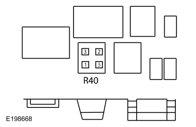
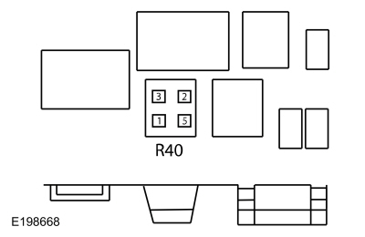
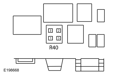
    Ford Fusion. Horn. Diagnosis and TestingHorn relay pin 2 socket Ford Fusion. Horn. Diagnosis and Testing Ground
    Ford Fusion. Horn. Diagnosis and TestingHorn relay pin 3 socket Ford Fusion. Horn. Diagnosis and Testing Ground

Is the voltage greater than 11 volts?
Yes GO to A5
No MAKE SURE that BJB fuse 48 (20A) (hybrid) or 50 (20A) (non-hybrid) is good. If good, CHECK OASIS for any applicable service articles: TSB, GSB, SSM or FSA. If a service article exists for this concern, STOP this test and FOLLOW the service article instructions. If no service articles apply to this concern, INSTALL a new BJB.
If not good, REFER TO the wiring diagrams to determine possible causes of the short circuit.
A5 CHECK THE HORN RELAY OUTPUT
  • Connect:
    Positive lead Measurement/Action Negative lead
    Ford Fusion. Horn. Diagnosis and TestingHorn relay pin 3 socket Ford Fusion. Horn. Diagnosis and Testing Ford Fusion. Horn. Diagnosis and TestingHorn relay pin 5 socket
  • Remove the fused jumper wire.

Does the horn sound?
Yes GO to A7
No GO to A6
A6 CHECK THE HORN RELAY OUTPUT CIRCUIT FOR AN OPEN
  • Disconnect the horn C1101.
  • Disconnect the BJB C1035B (non-hybrid).
  • Disconnect the BJB C1035A (hybrid).
  • Action:

    Non-hybrid


    Positive lead Measurement/Action Negative lead
    C1101-2 Ford Fusion. Horn. Diagnosis and Testing C1035B-50

    Hybrid


    Positive lead Measurement/Action Negative lead
    C1101-2 Ford Fusion. Horn. Diagnosis and Testing C1035A-46

Is the resistance less than 3 ohms?
Yes CHECK OASIS for any applicable service articles: TSB, GSB, SSM or FSA. If a service article exists for this concern, STOP this test and FOLLOW the service article instructions. If no service articles apply to this concern, INSTALL a new BJB.
No REPAIR the circuit.
A7 CHECK THE HORN RELAY CONTROL CIRCUIT FOR A SHORT TO VOLTAGE
  • Disconnect C2280C.
  • The ignition is on.
  • Action:
    Click to display the connectors
    Positive lead Measurement/Action Negative lead
    Horn relay pin 1 socket Ford Fusion. Horn. Diagnosis and Testing Ground

Is there voltage present?
Yes REPAIR the circuit.
No GO to A8
A8 CHECK THE HORN RELAY CONTROL CIRCUIT FOR AN OPEN
  • Ignition OFF.
  • Action:
    Click to display the connectors
    Positive lead Measurement/Action Negative lead
    Horn relay pin 1 socket Ford Fusion. Horn. Diagnosis and Testing C2280C-20

Is the resistance less than 3 ohms?
Yes GO to A14
No REPAIR the circuit.
A9 CHECK THE HORN SWITCH SIGNAL CIRCUIT
  • Ignition OFF.
  • Disconnect the SCCM C2414A.
  • Connect:
    Click to display connectors
    Positive lead Measurement/Action Negative lead
    C2414A-1 Ford Fusion. Horn. Diagnosis and Testing Ground
  • Remove the fused jumper wire.

Does the horn sound when the jumper wire is connected?
Yes GO to A11
No GO to A10
A10 CHECK THE HORN SWITCH SIGNAL CIRCUIT FOR AN OPEN
  • Disconnect C2280G.
  • Action:
    Click to display the connectors
    Positive lead Measurement/Action Negative lead
    C2414A-1 Ford Fusion. Horn. Diagnosis and Testing C2280G-18

Is the resistance less than 3 ohms?
Yes GO to A14
No REPAIR the circuit.
A11 CHECK THE CLOCKSPRING GROUND CIRCUIT FOR AN OPEN
  • Disconnect the clockspring C218A.
  • Action:
    Click to display the connectors
    Positive lead Measurement/Action Negative lead
    C218A-4 Ford Fusion. Horn. Diagnosis and Testing Ground

Is the resistance less than 3 ohms?
Yes GO to A12
No REPAIR the circuit.
A12 HORN SWITCH ISOLATION
  • Connect the SCCM C2414A.
  • Connect the clockspring C218A.
  • Remove the driver air bag.
    REFER to: Driver Air Bag (501-20B Supplemental Restraint System, Removal and Installation).
  • Connect:
    Click to display connectors
    Positive lead Measurement/Action Negative lead
    C217-1 Ford Fusion. Horn. Diagnosis and Testing C217-2
  • Remove the fused jumper wire.

Does the horn sound when the jumper wire is connected?
Yes CHECK OASIS for any applicable service articles: TSB, GSB, SSM or FSA. If a service article exists for this concern, STOP this test and FOLLOW the service article instructions. If no service articles apply to this concern, INSTALL a new driver airbag (including the horn switch).
REFER TO: Driver Airbag (501-20B Supplemental Restraint System, Removal and Installation).
No GO to A13
A13 CHECK HORN OPERATION WITH THE STEERING WHEEL WIRE HARNESS DISCONNECTED
  • Disconnect the clockspring C218B.
  • Connect:
    Click to display connectors
    Positive lead Measurement/Action Negative lead
    Clockspring C218B, pin 4, component side Ford Fusion. Horn. Diagnosis and Testing Clockspring C218B, pin 1, component side
  • Remove the fused jumper wire.

Does the horn sound when the jumper wire is connected?
Yes CHECK OASIS for any applicable service articles: TSB, GSB, SSM or FSA. If a service article exists for this concern, STOP this test and FOLLOW the service article instructions. If no service articles apply to this concern, INSTALL a new steering wheel (including the steering wheel wire harness).
REFER TO: Steering Wheel (211-04 Steering Column, Removal and Installation).
No CHECK OASIS for any applicable service articles: TSB, GSB, SSM or FSA. If a service article exists for this concern, STOP this test and FOLLOW the service article instructions. If no service articles apply to this concern, INSTALL a new clockspring.
REFER TO: Clockspring (501-20B Supplemental Restraint System, Removal and Installation). CHECK the system for normal operation. If the horn still does not operate, INSTALL a new SCCM.
REFER TO: Steering Column Control Module (SCCM) (211-05 Steering Wheel and Column Electrical Components, Removal and Installation).
A14 CHECK BCM (BODY CONTROL MODULE) OPERATION
  • Disconnect and inspect the BCM connectors.
  • Repair:
    • corrosion (install new connector or terminals - clean module pins)
    • damaged or bent pins - install new terminals/pins
    • backed-out pins - install new pins as necessary
  • Install the horn relay (if previously removed).
  • Reconnect the BCM connectors. Make sure they are fully seated and locked.
  • Operate the system and determine if the concern is still present.

Is the concern still present?
Yes CHECK OASIS for any applicable service articles: TSB, GSB, SSM or FSA. If a service article exists for this concern, STOP this test and FOLLOW the service article instructions. If no service article exists for this concern,
Ford Fusion. Horn. Diagnosis and TestingClick here to access the guided procedure (BCM).Ford Fusion. Horn. Diagnosis and Testing Internet Explorer version 11 or later is required to perform this Pinpoint test.
No The system is currently operating correctly. The concern may have been caused by module connections. ADDRESS the root cause of any connector or terminal issues.
Ford Fusion. Horn. Diagnosis and Testing Ford Fusion. Horn. Diagnosis and Testing PINPOINT TEST B: THE HORN IS ALWAYS ON

For circuit and connector information, refer to Cell 44 of the Wiring Diagrams.

Normal Operation and Fault Symptoms

REFER TO: Horn (413-06 Horn).

DTC Fault Trigger Conditions

Trouble Code Description Fault Trigger Condition
BCM B1323:11 Horn Switch: Short to Ground Sets when the BCM detects a short to ground in the horn switch input circuit.
BCM B1C55:14 Horn Relay: Short to Ground or Open This DTC sets when the BCM detects a short to ground in the horn relay control circuit.

Possible Sources

  • Wiring, Terminals or Connectors
  • Clockspring
  • Horn Relay
  • BJB
  • Steering Wheel
  • Driver Airbag (Horn Switch)
  • BCM
NOTICE: Use the correct probe adapter(s) when making measurements. Using incorrect probe adapter(s) may damage the connector.
B1 CHECK THE HORN RELAY OUTPUT

NOTICE: The following step uses a test lamp to simulate normal circuit loads. Use only the Rotunda test lamp (SGT27000) or a 250-300 mA incandescent test lamp. To prevent damage to the connector terminals, use the Rotunda Flex Probe kit for the test lamp probe connection to the vehicle. Do not use the test lamp probe directly on any connector.

  • Ignition OFF.
  • Disconnect the horn C1101.
  • Connect:
    Click to display connectors
    Positive lead Measurement/Action Negative lead
    C1101-1 Ford Fusion. Horn. Diagnosis and Testing C1101-2
  • Disconnect the horn relay.

Does the indicator lamp remain illuminated?
Yes GO to B2
No GO to B3
B2 CHECK THE HORN RELAY OUTPUT CIRCUIT FOR A SHORT TO VOLTAGE
  • Disconnect the BJB C1035B (non-hybrid).
  • Disconnect the BJB C1035A (hybrid).

Does the indicator lamp remain illuminated?
Yes REPAIR the circuit.
No GO to B3
B3 CHECK THE HORN RELAY
  • Install a known good relay.

Does the indicator lamp remain illuminated?
Yes REMOVE the known good relay. GO to B4.
No REMOVE the known good relay. INSTALL a new horn relay.
B4 ISOLATE THE BCM (BODY CONTROL MODULE) HORN SWITCH INPUT CIRCUIT
  • The ignition is on.
  • Using the diagnostic scan tool, view the BCM parameter identification (PID) data.
  • Monitor BCM PID HORN_SW.

Does the HORN_SW PID status display OFF?
Yes GO to B5
No GO to B7
B5 BCM (BODY CONTROL MODULE) ISOLATION SHORT TO GROUND
  • Ignition OFF.
  • Connect the horn relay.
  • Disconnect C2280C.

Does the indicator lamp remain illuminated?
Yes GO to B6
No GO to B11
B6 CHECK BCM (BODY CONTROL MODULE) HORN RELAY CONTROL CIRCUIT FOR SHORT TO GROUND
  • Disconnect BJB C1035A.

Does the indicator lamp remain illuminated?
Yes CHECK OASIS for any applicable service articles: TSB, GSB, SSM or FSA. If a service article exists for this concern, STOP this test and FOLLOW the service article instructions. If no service articles apply to this concern, INSTALL a new BJB.
No REPAIR the circuit.
B7 HORN SWITCH INPUT CIRCUIT ISOLATION
  • Ignition OFF.
  • Connect the horn relay.
  • Disconnect the SCCM C2414A.

Does the indicator lamp remain illuminated?
Yes GO to B8
No GO to B9
B8 CHECK BCM (BODY CONTROL MODULE) HORN SWITCH INPUT CIRCUIT FOR SHORT TO GROUND
  • Disconnect C2280G.

Does the indicator lamp remain illuminated?
Yes GO to B11
No GO to B9
B9 DRIVER AIR BAG ISOLATION
  • Remove the driver air bag.
    REFER to: Driver Air Bag (501-20B Supplemental Restraint System, Removal and Installation).
  • Connect the SCCM C2414A.

Does the indicator lamp remain illuminated?
Yes GO to B10
No CHECK OASIS for any applicable service articles: TSB, GSB, SSM or FSA. If a service article exists for this concern, STOP this test and FOLLOW the service article instructions. If no service articles apply, INSTALL a new driver air bag.
REFER TO: Driver Air Bag (501-20B Supplemental Restraint System, Removal and Installation).
B10 STEERING WHEEL WIRING ISOLATION
  • Connect the clockspring C218B.

Does the indicator lamp remain illuminated?
Yes CHECK OASIS for any applicable service articles: TSB, GSB, SSM or FSA. If a service article exists for this concern, STOP this test and FOLLOW the service article instructions. If no service articles apply, INSTALL a new clockspring.
REFER TO: Clockspring (501-20B Supplemental Restraint System, Removal and Installation). CHECK the system for normal operation. If the indicator lamp remains on, INSTALL a new SCCM.
REFER TO: Steering Column Control Module (SCCM) (211-05 Steering Wheel and Column Electrical Components, Removal and Installation).
No CHECK OASIS for any applicable service articles: TSB, GSB, SSM or FSA. If a service article exists for this concern, STOP this test and FOLLOW the service article instructions. If no service articles apply to this concern, INSTALL a new steering wheel (including the steering wheel wire harness).
REFER TO: Steering Wheel (211-04 Steering Column, Removal and Installation).
B11 CHECK THE BCM (BODY CONTROL MODULE) OPERATION
  • Disconnect and inspect the BCM connectors.
  • Repair:
    • corrosion (install new connector or terminals - clean module pins)
    • damaged or bent pins - install new terminals/pins
    • backed-out pins - install new pins as necessary
  • Reconnect the BCM connectors. Make sure they are fully seated and locked.
  • Connect the horn C1101.
  • Operate the system and determine if the concern is still present.

Is the concern still present?
Yes CHECK OASIS for any applicable service articles: TSB, GSB, SSM or FSA. If a service article exists for this concern, STOP this test and FOLLOW the service article instructions. If no service article exists for this concern,
Ford Fusion. Horn. Diagnosis and TestingClick here to access the guided procedure (BCM).Ford Fusion. Horn. Diagnosis and Testing Internet Explorer version 11 or later is required to perform this Pinpoint test.
No The system is currently operating correctly. The concern may have been caused by module connections. ADDRESS the root cause of any connector or terminal issues.

Test yourself

A quick Ford Fusion quiz: every answer comes with an explanation and a link to the manual page.