Front Suspension
SPECIFICATIONS
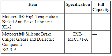
Material
Torque Specifications
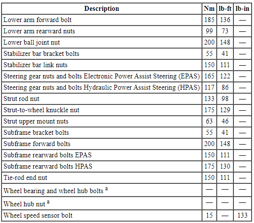
a Refer to the procedure in this section.
DESCRIPTION AND OPERATION
Front Suspension
The front suspension consists of the following components:
- Wheel bearing and wheel hubs
- Wheel studs
- Lower arms
- Stabilizer bar
- Stabilizer bar links
- Struts
- Springs
- Wheel knuckles
The front suspension utilizes a MacPherson strut system.
This suspension system incorporates a strut assembly that takes the place of the upper arm and ball joint. The strut carries out the function of a shock absorber and is encompassed by a coil spring. The strut and spring assembly supports the weight of the vehicle and is also the pivot point for the steering knuckle. This system uses a lower control arm and ball joint for the lower (unloaded) pivot point of the steering knuckle.
REMOVAL AND INSTALLATION
Front Suspension - Exploded View
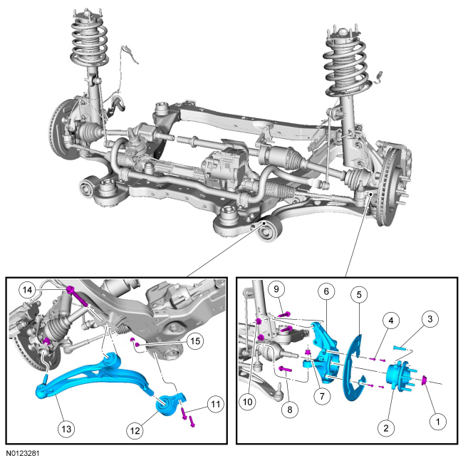
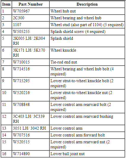
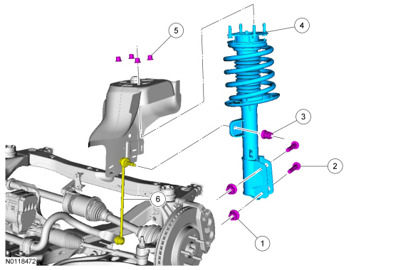
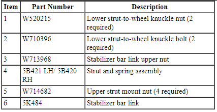
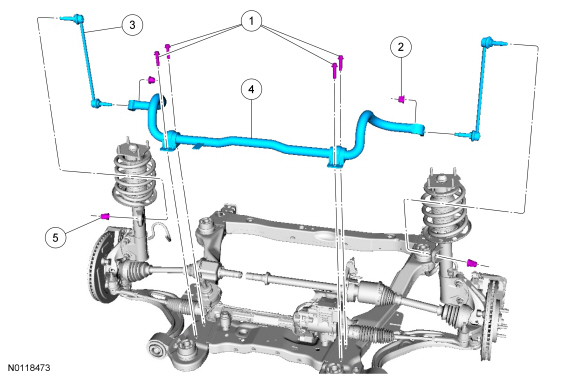
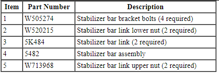
- For additional information, refer to the procedures in this section.
Wheel Bearing and Wheel Hub
General Equipment
- Front wheel hub remover
Removal
NOTICE: Suspension fasteners are critical parts because they affect performance of vital components and systems and their failure may result in major service expense. New parts must be installed with the same part numbers or equivalent part, if replacement is necessary. Do not use a replacement part of lesser quality or substitute design. Torque values must be used as specified during reassembly to make sure of correct retention of these parts.
NOTE: Removal steps in this procedure may contain installation details.
- Remove the wheel and tire. Refer to Section 204-04.
- NOTE: Apply the brake to keep the halfshaft from rotating.
NOTE: Do not discard the wheel hub nut at this time.
- Remove the brake disc. Refer to Section 206-03.
- NOTE: Push the halfshaft into the wheel hub to gain access for the removal of the wheel bearing and wheel hub bolts.
General equipment: Front wheel hub remover
- NOTICE: The wheel knuckle bore must be clean enough to allow the wheel bearing and wheel hub to seat completely by hand. Do not press or draw the wheel hub and bearing into place or damage to the bearing may occur.
NOTICE: Make sure the wheel hub-to-wheel knuckle mating surfaces are clean and free of any adhesive. Failure to clean the adhesive from both surfaces may cause bearing damage.
Installation
- Finger tight at this stage.
- NOTE: Push the halfshaft into the wheel hub to gain access for tightening the wheel bearing and wheel hub bolts.
- Tighten the new bolts to 133 N·m in the sequence shown.
- Install the brake disc. Refer to Section 206-03.
- NOTICE: Do not tighten the front wheel hub nut with the vehicle on the ground. The nut must be tightened to specification before the vehicle is lowered onto the wheels. Wheel bearing damage will occur if the wheel bearing is loaded with the weight of the vehicle applied.
NOTE: Apply the brake to keep the halfshaft from rotating and use the previously removed wheel hub nut, seat the halfshaft.
- Tighten the previously removed nut to 350 N·m
- NOTICE: The wheel hub nut contains a one time locking chemical that is activated by the heat created when it is tightened. Install and tighten the new wheel hub nut to specification within 5 minutes of starting it on the threads. Always install a new wheel hub nut after loosening or when not tightened within the specified time or damage to the components can occur.
- Tighten the new nut to 350 N·m
- Install the wheel and tire. Refer to Section 204-04.
Wheel Studs
Special Tool(s)

Removal
- NOTICE: Suspension fasteners are critical parts because they affect performance of vital components and systems and their failure may result in major service expense. New parts must be installed with the same part numbers or equivalent part, if replacement is necessary. Do not use a replacement part of lesser quality or substitute design. Torque values must be used as specified during reassembly to make sure of correct retention of these parts.
NOTE: Make sure the steering wheel is in the unlocked position.
Remove the brake disc. Refer to Section 206-03. - Discard the specified component. Follow local disposal regulations.
- Using the C-Frame and Screw Installer/Remover, remove the wheel stud.
Installation
- NOTE: Make sure to use washers that have an ID that is larger than the OD of the wheel stud serrations. Use enough washers (approximately 4) to allow the wheel stud to fully seat against the hub flange.
Position the wheel stud in the flange, making sure the serrations on the stud line up with the serrations in the flange. Install the washers and a reversed wheel nut.
- NOTICE: Do not use power tools to install the wheel stud or damage to the flange may occur.
Tighten the wheel nut until the stud is seated against the hub flange.
- Remove the wheel nut and the washers. Discard the wheel nut.
- To install, tighten to 165 N·m in the sequence shown.
- Install the brake disc. Refer to Section 206-03.
Lower Arm
Removal and Installation
NOTICE: Suspension fasteners are critical parts because they affect performance of vital components and systems and their failure may result in major service expense. New parts must be installed with the same part numbers or equivalent part, if replacement is necessary. Do not use a replacement part of lesser quality or substitute design. Torque values must be used as specified during reassembly to make sure of correct retention of these parts.
- Remove the wheel and tire. For additional information, refer to Section 204-04.
- NOTE: Use the hex-holding feature to prevent the stud from turning while removing the nut.
Using a crowfoot wrench, remove and discard the lower ball joint nut.
- To install, tighten to 200 N·m.
- NOTICE: Use care when releasing the lower arm and knuckle into the resting position or damage to the ball joint seal may occur.
Push the lower arm downward until the ball joint is clear of the wheel knuckle.
- Remove and discard the lower arm forward bolt.
- To install, tighten the new bolt to 185 N·m.
- Remove and discard the lower arm rearward nuts and bolts.
- To install, tighten the new nuts to 99 N·m.
- Install the new lower arm rearward bolts from the bottom of the lower arm bushing with the nuts on top.
- If necessary, remove the lower arm rearward bushing. For additional information, refer to Lower Arm Bushing in this section.
- NOTICE: The lower arm forward bolt must be tightened with the weight of the vehicle on the wheels and tires or damage to the bushings may occur.
To install, reverse the removal procedure.
Lower Arm Bushing
Special Tool(s)
Removal
- Remove the lower arm. For additional information, refer to Lower Arm in this section.
- Index-mark the bushing-to-lower arm position for reference during the installation procedure.
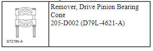
- NOTE: The Drive Pinion Bearing Cone Remover is used to secure the lower arm bushing while separating the bushing from the lower arm.
Using the Drive Pinion Bearing Cone Remover, a suitable press and adapters, remove the lower arm bushing.
Installation
- NOTE: The Drive Pinion Bearing Cone Remover is used to clamp and hold the lower arm while installing the bushing.
Install the Drive Pinion Bearing Cone Remover onto the lower arm.
- Transfer the index mark to the new lower arm bushing.
- NOTE: The Drive Pinion Bearing Cone Remover is used to clamp and hold the lower arm while installing the bushing.
Align the index marks and using the Drive Pinion Bearing Cone Remover, a suitable press and adapters, install a new lower arm bushing.
- Install the lower arm. For additional information, refer to Lower Arm in this section.
Stabilizer Bar
Removal and Installation
NOTICE: Suspension fasteners are critical parts because they affect performance of vital components and systems and their failure may result in major service expense. New parts must be installed with the same part numbers or equivalent part, if replacement is necessary. Do not use a replacement part of lesser quality or substitute design. Torque values must be used as specified during reassembly to make sure of correct retention of these parts.
NOTE: Make sure the steering wheel is in the unlocked position.
NOTE: The stabilizer bushing and bracket are part of the stabilizer bar assembly. The stabilizer bar will not turn easily in the bushing.
All vehicles
- With the vehicle in NEUTRAL, position it on a hoist. For additional information, refer to Section 100-02.
- Remove the wheel and tire. For additional information, refer to Section 204-04.
- Disconnect the Heated Oxygen Sensor (HO2S) electrical connector and unclip the connector from the subframe.
All-Wheel Drive (AWD) vehicles
- Remove the exhaust Y-pipe. For additional information, refer to Section 309-00.
All vehicles
- NOTICE: Do not use power tools to remove the stabilizer bar link nut. Damage to the stabilizer link ball joint or boot may occur.
NOTE: To remove the stabilizer bar link nut, first loosen the nut, then use the hex-holding feature to prevent the ball joint from turning while removing the stabilizer bar link nut.
Remove and discard the stabilizer bar link lower nuts.- To install, tighten the new nuts to 150 N·m.
- NOTE: No special tools are necessary to separate the tie rod from the front knuckle; use a mallet to loosen the joint.
Remove and discard both tie-rod end nuts and separate the tie-rod ends from the knuckles.
- To install, tighten the new nuts to 150 N·m.
- NOTE: Install the new lower arm rearward bolts from the bottom of the lower arm bushing with the nuts on top.
Remove and discard the 4 lower arm rearward nuts and bolts.
- To install, tighten the new bolts to 99 N·m.
- Remove and discard the 2 lower arm forward bolts.
Position both lower arms aside.- To install, tighten the new bolts to 185 N·m.
- Using a suitable screw-type jackstand, support the rear of the subframe.
- Remove the 2 steering gear nuts and bolts.
- Vehicles with Electronic Power Assist Steering (EPAS)
- To install, tighten the nuts to 165 N·m.
- Vehicles with Hydraulic Power Assist Steering (HPAS)
- To install, tighten the new nuts to 117 N·m.
- Vehicles with Electronic Power Assist Steering (EPAS)
- Remove and discard the 4 subframe bracket bolts.
- To install, tighten the new bolts to 55 N·m.
- Remove and discard the subframe forward bolts.
- To install, tighten the new bolts to 200 N·m.
- Remove and discard the subframe rearward bolts.
- Vehicles with EPAS
- To install, tighten the new bolts to 150 N·m.
- Vehicle with HPAS
- To install, tighten the new bolts to 175 N·m.
- Vehicles with EPAS
- Lower the rear of the subframe approximately 51 mm (2 in).
- Remove and discard the LH and RH stabilizer bar bracket bolts.
- To install, tighten the new bolts to 55 N·m.
- Remove the stabilizer bar by guiding it between the subframe and the steering gear toward the RH side of the vehicle.
- To install, reverse the removal procedure.
Stabilizer Bar Link
Removal and Installation
NOTICE: Suspension fasteners are critical parts because they affect performance of vital components and systems and their failure may result in major service expense. New parts must be installed with the same part numbers or equivalent part, if replacement is necessary. Do not use a replacement part of lesser quality or substitute design. Torque values must be used as specified during reassembly to make sure of correct retention of these parts.
- With the vehicle in NEUTRAL, position it on a hoist. For additional information, refer to Section 100-02.
NOTICE: Do not use power tools to remove the stabilizer bar link nuts. Damage to the stabilizer bar link ball joints or boots may occur.
NOTE: To remove the stabilizer bar link nuts, first loosen the nuts, then use the hex-holding feature to prevent the stabilizer bar link ball joints from turning while removing the stabilizer bar link nuts.
- Remove and discard the stabilizer bar link lower nut.
- To install, tighten the new nut to 150 N·m.
- Remove and discard the stabilizer bar link upper nut.
- To install, tighten the new nut to 150 N·m.
- Remove the stabilizer bar link.
- NOTE: To install the nuts, use the hex-holding feature to prevent the stabilizer link ball joints from turning while installing the nuts until snug. Finally, tighten the nuts using a socket and a torque wrench.
To install, reverse the removal procedure.
Wheel Knuckle
Special Tool(s)

Removal
NOTICE: Suspension fasteners are critical parts because they affect performance of vital components and systems and their failure may result in major service expense. New parts must be installed with the same part numbers or equivalent part, if replacement is necessary. Do not use a replacement part of lesser quality or substitute design. Torque values must be used as specified during reassembly to make sure of correct retention of these parts.
- Remove the wheel and tire. For additional information, refer to Section 204-04.
- NOTE: Do not discard the wheel hub nut at this time.
Remove the wheel hub nut.
- Remove the brake disc. For additional information, refer to Section 206-03.
- NOTE: No special tools are necessary to separate the tie rod from the front knuckle; use a mallet to loosen the joint.
Remove and discard the tie-rod end nut, then separate the tie rod from the wheel knuckle.
- Remove the bolt and the wheel speed sensor from the wheel knuckle. Position the wheel speed sensor aside.
- NOTE: Use the hex-holding feature to prevent the stud from turning while removing the nut.
Using a crowfoot wrench, remove and discard the lower ball joint nut.
- Push the lower arm downward until the ball joint is clear of the wheel knuckle.
- NOTICE: Do not allow the halfshaft to move outboard. Overextension of the tripod Constant Velocity (CV) joint may result in separation of internal parts, causing failure of the halfshaft.
Using the Front Wheel Hub Remover, press the halfshaft from the wheel bearing and hub. Support the halfshaft in a level position.
- Remove and discard the strut-to-wheel knuckle nut and flagbolt.
- Remove the wheel knuckle.
- If necessary, remove the wheel hub and bearing. For additional information, refer to Wheel Bearing and Wheel Hub in this section.
Installation
- Position the wheel knuckle and install a new strut-to-wheel knuckle nut and flagbolt.
- Tighten to 175 N·m.
- While supporting the halfshaft in a level position, install the halfshaft into the wheel bearing and hub.
- NOTICE: Use care not to damage the ball joint seal while installing the ball joint stud into the wheel knuckle.
Push the lower arm downward and install the ball joint stud into the wheel knuckle.
- NOTE: Use the hex-holding feature to prevent the stud from turning while installing the nut.
Using a crowfoot wrench, install the new lower ball joint nut.
- Tighten to 200 N·m.
- Position the wheel speed sensor and install the bolt.
- Tighten to 15 N·m.
- Position the tie-rod end stud into the wheel knuckle and install a new tie-rod end nut.
- Tighten to 150 N·m.
- Install the brake disc. For additional information, refer to Section 206-03.
- NOTICE: Do not tighten the front wheel hub nut with the vehicle on the ground. The nut must be tightened to specification before the vehicle is lowered onto the wheels. Wheel bearing damage will occur if the wheel bearing is loaded with the weight of the vehicle applied.
NOTE: Apply the brake to keep the halfshaft from rotating.
Using the previously removed hub nut, seat the halfshaft.- Tighten to 350 N·m.
- Remove and discard the hub nut.
- NOTICE: The wheel hub nut contains a one-time locking chemical that is activated by the heat created when it is tightened. Install and tighten the new wheel hub nut to specification within 5 minutes of starting it on the threads. Always install a new wheel hub nut after loosening or when not tightened within the specified time or damage to the components can occur.
NOTE: Apply the brake to keep the halfshaft from rotating.
Install a new hub nut.- Tighten to 350 N·m.
- Install the wheel and tire. For additional information, refer to Section 204-04.
Strut and Spring Assembly
Removal
WARNING: Do not apply heat or flame to the shock absorber or strut tube. The shock absorber and strut tube are gas pressurized and could explode if heated. Failure to follow this instruction may result in serious personal injury.
WARNING: Keep all body parts clear of shock absorbers or strut rods. Shock absorbers or struts can extend unassisted. Failure to follow this instruction may result in serious personal injury.
NOTICE: Suspension fasteners are critical parts that affect the performance of vital components and systems. Failure of these fasteners may result in major service expense. Use the same or equivalent parts if replacement is necessary. Do not use a replacement part of lesser quality or substitute design. Tighten fasteners as specified.
- Remove the wheel and tire. Refer to Section 204-04.
Installation
- Tighten to 63 N·m.
- Tighten to 225 N·m.
- Tighten to 150 N·m.
- Install the wheel and tire. Refer to Section 204-04.
- Check front camber adjustment. Refer to Section 204-00
DISASSEMBLY AND ASSEMBLY
Strut and Spring Assembly
Material


Disassembly and Assembly
WARNING: Do not apply heat or flame to the shock absorber or strut tube. The shock absorber and strut tube are gas pressurized and could explode if heated. Failure to follow this instruction may result in serious personal injury.
WARNING: Keep all body parts clear of shock absorbers or strut rods. Shock absorbers or struts can extend unassisted. Failure to follow this instruction may result in serious personal injury.
NOTICE: Suspension fasteners are critical parts because they affect performance of vital components and systems and their failure may result in major service expense. New parts must be installed with the same part numbers or equivalent part, if replacement is necessary. Do not use a replacement part of lesser quality or substitute design. Torque values must be used as specified during reassembly to make sure of correct retention of these parts.
NOTICE: When installing a suitable spring compressor, use care not to damage the spring coating.
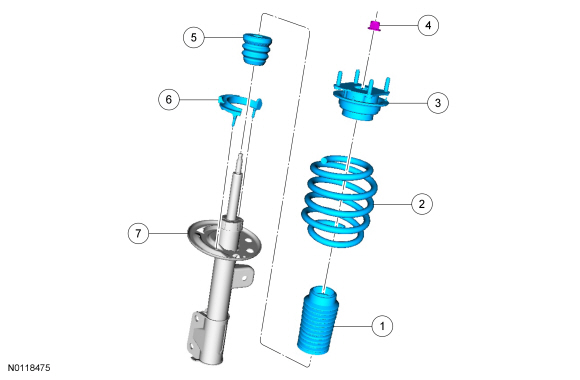
- Remove the strut and spring assembly. For additional information, refer to Strut and Spring Assembly in this section.
- WARNING: Coil springs and strut assemblies are compressed under extreme load. Always use a spring compressor for disassembly. Follow procedure instructions carefully and make sure the spring compressor has the correct spring plates or adapters. Failure to follow these instructions may result in serious personal injury.
NOTE: Use the hex-holding feature to prevent the shock absorber rod from turning while removing or installing the strut rod nut.
Using a suitable spring compressor, slightly compress the spring to remove initial tension. Using the hex-holding feature to hold the strut rod, loosen the strut rod nut. Continue to compress the spring until tension is relieved. - Using the hex-holding feature to hold the strut rod, remove and discard the strut rod nut.
- To install, tighten the new nut to 133 N·m.
- Inspect the upper strut mount and seat-bearing assembly. The spring insulator should not be cracked, torn or distorted. The strut bearing should turn freely without grinding. Install a new upper strut mount, if necessary.
- Decompress and remove the spring. Remove the dust boot and jounce bumper.
- To maintain wheel camber:
- position the notch and arrow on the upper strut mount outboard opposite the center of the mounting flanges on the strut.
- To adjust camber +0.5 degrees:
- position the notch and arrow on the upper strut mount inboard aligned with the center of the mounting flanges on the strut.
- To maintain wheel camber:
- NOTICE: Do not overtighten the strut rod nut. Damage to the nut or strut rod may occur.
NOTE: Make sure the spring is correctly seated in both spring seats.
NOTE: During assembly, apply the specified silicone brake grease to the strut rod and the top and sides of the outermost part of the dust boot.
To assemble, reverse the disassembly procedure.
Test yourself
A quick Ford Taurus quiz: every answer comes with an explanation and a link to the manual page.