Powertrain
Installation
In this manual: Powertrain
56steps
~336min
4/5difficulty
Done 0 of 56
Engine
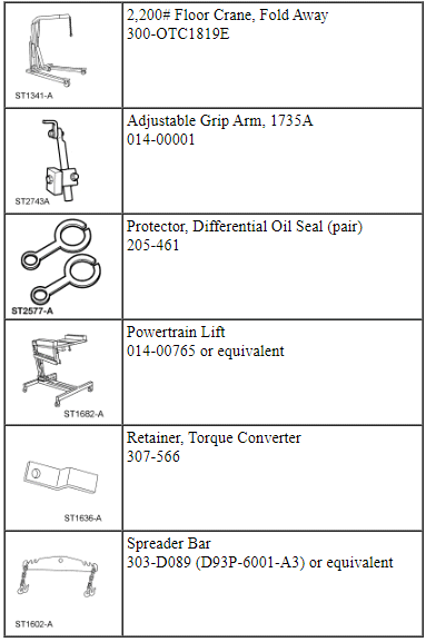
Special Tool(s)
Material

- Lubricate the torque converter pilot hub with Multi-Purpose Grease.
- Remove the Torque Converter Retainer and bolt.
- NOTE: Align the torque converter stud marked during removal with the flexplate.
Using the Floor Crane and Spreader Bar, assemble the engine and transaxle.
- Install the transaxle-to-engine bolt and 2 stud bolts.
- Tighten to 48 N·m.
- Install the 3 engine-to-transaxle bolts.
- Tighten to 48 N·m.
- Install the 3 transaxle-to-engine bolts.
- Tighten to 48 N·m.
- Connect the 2 transaxle electrical connectors.
- Attach the 2 wiring harness retainers.
- Attach the 2 wiring harness retainers.
- Attach the 2 wiring harness retainers.
- Using the Floor Crane and Spreader Bar, position the engine and transaxle on the Powertrain Lift.
- NOTE: Position a block of wood under the transaxle.
Install the Powertrain Lift and Adjustable Grip Arms.
- Connect the PCV tube to the turbocharger inlet pipe.
- Install the wire terminal and nut on the generator.
- Tighten to 17 N·m and install the cap.
- Connect the wire harness electrical connector.
- Attach the 4 wiring harness retainers to the engine.
- Connect the coolant hose to the transmission fluid temperature control valve.
- NOTICE: Only rotate the engine in a clockwise direction or engine damage will occur.
Install the 4 torque converter nuts.
- Tighten to 40 N·m.
- Install the starter insulator.
- Install the starter and the 2 stud bolts.
- Tighten to 35 N·m.
- Install the 2 starter wire terminals, the ground wire and the 3 nuts.
- Tighten the ground wire nut to 18 N·m.
- Tighten the large starter wire terminal nut to 12 N·m.
- Tighten the small starter wire terminal nut to 5 N·m.
- Install the starter cable cover.
- Raise the engine and transaxle assembly into the vehicle.
- Install the engine mount, the 4 nuts and the 3 bolts.
- Tighten the bolts to 90 N·m and the nuts to 125 N·m.
- Install the engine mount, the 4 nuts and the 3 bolts.
- Install the transaxle support insulator bracket, the 3 nuts and the bolt.
- Tighten the 3 nuts to 63 N·m.
- Tighten the bolt to 80 N·m.
- Install the transaxle support insulator through bolt and nut.
- Tighten to 175 N·m.
- Install the A/C compressor, the 2 bolts and the stud.
- Tighten the bolts to 25 N·m and the stud to 9 N·m.
- Install the nut and tighten to 25 N·m.
- Connect the 2 A/C compressor electrical connectors.
- Install the A/C tube bracket nut.
- Tighten to 15 N·m.
- Install the A/C compressor drive belt. For additional information, refer to Section 303-05.
- NOTICE: Make sure to install the correct circlip for this application. Failure to use the correct diameter circlip may result in shaft removal concerns or shaft damage during vehicle operation.
Install a new circlip.
- Install Differential Oil Seal Protector on the LH halfshaft seal.
- NOTICE: The sharp edges on the halfshaft splines can slice or puncture the oil seal. Use care when inserting the halfshaft into the transaxle or damage to the seal may occur.
Push the LH halfshaft into the transaxle so the circlip locks into the differential side gear. Pull the halfshaft inner end to make sure the circlip is locked.
- Install the RH halfshaft in the transaxle and engage the halfshaft splines with the transaxle side gears and install the 2 halfshaft nuts.
- Tighten to 25 N·m.
- NOTE: Lubricate the engine oil filter gasket with clean engine oil prior to installing the oil filter.
Install a new engine oil filter.
- Tighten to 8 N·m plus an additional 180 degrees.
- Install the 2 transaxle-to-oil pan bolts.
- Tighten to 48 N·m.
- Connect the transaxle cooling tubes.
- Install the 2 secondary latches onto the transaxle fluid cooler tubes.
- Install the front subframe. For additional information, refer to Section 502-00.
- Install the engine roll restrictor. For additional information, refer to Section 307-01B.
- Install the catalytic converter. For additional information, refer to Section 309-00
- Install the underbody shield and the 4 retainers.
- Slide the wiring harness onto the bulkhead and verify the retaining tab is engaged.
- Connect the 2 wiring harness electrical connectors.
- Install the ground wire and bolt to the RH inner fender.
- Tighten to 11 N·m.
- Connect the EVAP tube to the EVAP purge valve. For additional information, refer to Section 310-00.
- Connect the fuel supply tube quick connect coupling. For additional information, refer to Section 310-00.
- Connect the CAC inlet tube.
- Tighten clamp to 8 N·m.
- Attach the 2 wiring harness retainers to the valve cover stud bolts.
- Connect the lower radiator hose to the engine.
- Connect the coolant hose to the degas bottle.
- Connect the CAC outlet tube.
- Tighten clamp to 5 N·m.
- Connect the transaxle selector lever cable end to the manual control lever and install the 2 bracket bolts.
- Tighten to 25 N·m.
- Connect the vacuum tube quick connect coupling to the power brake booster. For additional information, refer to Section 310-00.
- Attach the vacuum tube retaining clip.
- Connect the upper radiator hose and the heater hose.
- Connect the heater hose quick connect coupling.
- Attach the hoses to the 2 retaining clips.
- Connect the wiring harness electrical connector.
- Install the ground wire and nut.
- Tighten to 9 N·m.
- Connect the power feed to the battery terminal and install the nut.
- Tighten to 9 N·m.
- Install the battery tray. For additional information, refer to Section 414-01.
- Install the engine ACL and ACL outlet pipe assembly. For additional information, refer to Section 303-12.
- Install the cowl panel grille. For additional information, refer to Section 501-02.
- Fill the engine with clean engine oil.
- Fill and bleed the engine cooling system. For additional information, refer to Section 303-03.
- After completing the repairs, use the scan tool to perform the Misfire Monitor Neutral Profile Correction procedure, following the on-screen instructions.
Test yourself
A quick Ford Taurus quiz: every answer comes with an explanation and a link to the manual page.
Was this page helpful?