Engine removal is not necessary for this procedure.
Use fender covers to avoid damaging painted surfaces.
To prevent damage to the cylinder head, wait until the engine coolant temperature drops below normal temperature (20 °C [68°F]) before removing it.
When handling the metal gasket, be careful not to bend the gasket or damage the gasket contact surface.
To avoid damage, carefully disconnect the wiring connectors by holding the connector body.
Label all wires and hoses to avoid incorrect connection.
Turn the crankshaft pulley so that the No. 1 piston is at TDC (top dead center).
Remove the engine cover. (Refer to Engine and Transaxle Assembly - "Engine Cover")
Remove the air duct and air cleaner assembly. (Refer to Intake and Exhaust System - "Air Cleaner")
Remove the battery. (Refer to Engine Electrical System - "Battery")
Remove the ECM (Engine Control Module). (Refer to Engine Control/Fuel System - "Engine Control Module (ECM)")
Remove the battery tray. (Refer to Engine Electrical System - "Battery")
Remove the engine compartment cover. (Refer to Engine and Transaxle Assembly - "Engine Compartment Under Cover")
Drain the engine coolant. (Refer to Cooling System — Engine Coolant)
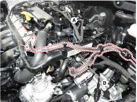
Disconnect the fuel hose (A) and the hose (B) of the purge control solenoid valve (PCSV).
Remove the vacuum hose (A).
Tightening torque: 9.8 ~ 11.8 N·m
Remove the condenser (A).
Tightening torque: 9.8 ~ 11.8 N·m
Remove the bracket (A) for the purge control solenoid valve (PCSV).
Tightening torque: 9.8 ~ 11.8 N·m
Remove the delivery pipe. (Refer to Engine Control / Fuel System — Delivery Pipe)
Remove the cylinder head cover. (Refer to Cylinder Head Assembly - Cylinder Head Cover)
Remove the timing chain. (Refer to Valve Timing System - Timing Chain)
Remove the exhaust manifold. (Refer to Intake and Exhaust Systems — Exhaust Manifold)
Remove the intake manifold. (Refer to Intake and Exhaust Systems — Intake Manifold)
Remove the water temperature control assembly. (Refer to Cooling System — Water Temperature Control Assembly)
Remove the heater hose. (Refer to Cooling System — Thermostat)
Remove the intake CVVT assembly (A) and the exhaust CVVT assembly (B).
When removing the CVVT assembly bolt, hold the camshaft with a wrench to prevent it from rotating.
Remove the camshaft.
Remove the camshaft bearing cap (A) by loosening the bolts in the specified sequence.
Remove the camshafts (A).
Remove the cam holder (A).
Remove the hydraulic lash adjuster (HLA) (A) and the rocker arm (B).
The HLA and rocker arm must be stored together as pairs after removal and during reinstallation.
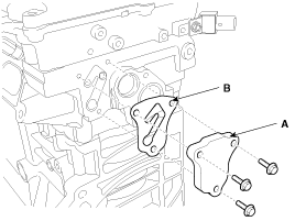
Remove the oil control adapter (A) with the gasket (B).
Remove the intake oil control valve (OCV) (A).
Remove the exhaust oil control valve (OCV) (A).
Remove the rear engine mounting bracket (A).
Remove the spark plugs. (Refer to Engine Electrical System - "Spark Plug")
Remove the cylinder head.
Using a torx socket (12 point), loosen and remove the cylinder head bolts evenly in several passes in the specified sequence.
Cylinder head distortion or cracking may result if the bolts are loosened in the wrong order.
Lift the cylinder head (A) off the dowels on the cylinder block and place the cylinder head on wooden blocks on the workbench.
Be careful not to damage the contact surfaces of the cylinder head and cylinder block.
Remove the cylinder head gasket (B).
Disassembly
Identify the valves and valve springs as they are removed so that each part can be reinstalled in its original position.
Remove the valves.
Using SST (09222-3K000, 09222-2A100), compress the valve spring and remove the retainer locks (A).
When installing the SST, insert the front support (A) directly into the bolt hole on the cylinder head.
Do not depress the valve retainer more than 12 mm (0.47 in.).
Remove the spring seat (B).
Remove the valve spring (C).
Remove the valve (D).
Using needle-nose pliers, remove the valve stem seal (E).
Do not reuse the valve stem oil seals.
Inspection
Cylinder head cover
Inspect for flatness.Using a precision straightedge and feeler gauge, measure the cylinder block and manifold contact surfaces for warpage. Cylinder head gasket surface flatness: Overall less than 0.05 mm (0.0020 in.). Less than 0.02 mm (0.0008 in.) per 100 mm (3.9370 in.) x 100 mm (3.9370 in.) area.
Manifold mounting surface flatness: Less than 0.10 mm (0.0039 in.)
Inspect for cracks. Check the combustion chamber, intake ports, exhaust ports and the cylinder head surface for cracks. If any cracks are found, replace the cylinder head.
Inspect the valve stems and valve guides.
Using a caliper gauge, measure the inside diameter of the valve guide. Valve guide inside diameter Intake: 5.500 - 5.512 mm (0.21654 - 0.21701 in.) Exhaust: 5.500 - 5.512 mm (0.21654 - 0.21701 in.)
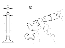
Using a micrometer, measure the diameter of the valve stem. Valve stem outside diameter Intake: 5.465 - 5.480 mm (0.21516 - 0.21575 in.) Exhaust: 5.458 - 5.470 mm (0.21488 - 0.21535 in.)
Subtract the valve stem diameter measurement from the valve guide inside diameter measurement. If the clearance is greater than specified, replace the valve or the cylinder head. Valve stem-to-guide clearance [Standard] Intake: 0.020 - 0.047 mm (0.00079 - 0.00185 in.) Exhaust: 0.030 - 0.054 mm (0.00118 - 0.00213 in.)
Inspect the valves.
Make sure the valve face is ground to the correct valve face angle.
Check the valve face for wear. If the valve face is worn, replace the valve.
Check the valve head margin thickness. If the margin is less than specified, replace the valve.
Margin thickness [Standard] Intake: 1.30 mm (0.0512 in.) Exhaust: 1.26 mm (0.0496 in.)
Check the valve length. Valve length [Standard] Intake: 102.22 mm (4.0244 in.) Exhaust: 104.04 mm (4.0961 in.) [Limit] Intake: 101.97 mm (4.0146 in.) Exhaust: 103.79 mm (4.0862 in.)
Check the valve stem tip for wear. If the valve stem tip is worn, replace the valve.
Inspect the valve seats and valve guides.
Check the valve seat for signs of overheating and improper contact with the valve face. If the valve seat is worn, replace the cylinder head.
Check the valve guide for wear. If the valve guide is worn, replace the cylinder head.
Inspect the valve springs.
Using a steel square, measure the valve spring squareness.
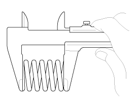
Using a caliper gauge, measure the valve spring free length. If the free length is not as specified, replace the valve spring. Valve spring [Standard] Free length: 45.93 mm (1.8083 in.) Load: 19.6 ± 1.0 kg / 37.0 mm (43.21 ± 2.20 lb / 1.4567 in.) 45.7 ± 1.8 kg / 27.0 mm (100.75 ± 3.97 lb / 1.0630 in.) Angle of squareness: Less than 1.5°
Valve and Valve Spring — Hydraulic Lash Adjuster (HLA): When the HLA is filled with engine oil, hold A and press B by hand. If B moves, replace the HLA.
Symptom
Possible Cause
Action
1. Temporary noise when starting a cold engine
Normal
This noise will disappear after the engine oil reaches normal pressure.
2. Continuous noise when starting the engine after it has been parked for more than 48 hours.
Oil leakage from the HLA high-pressure chamber allowing air to enter
The noise will disappear within 15 minutes with the engine running at 2000-3000 rpm. If it does not disappear, see step 7 below.
3. Continuous noise when starting the engine for the first time after cylinder head overhaul.
Insufficient oil in the cylinder head oil passage
4. Continuous noise when starting the engine after excessive cranking with the starter.
Oil leakage from the HLA high-pressure chamber allowing air to enter
Insufficient oil in the HLA
5. Continuous noise while the engine is running after HLA replacement
Do not run the engine above 3000 rpm, as this may damage the HLA.
6. Continuous noise at idle after high engine speed operation.
Engine oil level is too high or too low
Check the oil level.
Drain or add oil as necessary.
Excessive air in the oil at high engine speed
Check the oil supply system.
Deteriorated oil
Check the oil quality. If deteriorated, replace with the specified type.
7. Noise continues for more than 15 minutes
Low oil pressure
Check the oil pressure and the oil supply system to each engine component.
Faulty HLA
Remove the cylinder head cover and press the HLA by hand. If it moves, replace the HLA.
Installation
Thoroughly clean all parts to be assembled.
Before installing parts, apply new engine oil to all sliding and rotating surfaces.
Replace the oil seals with new ones.
Install the valves.
Using SST (09222-2E000), install a new stem seal (A).
Do not reuse the old valve stem oil seals.
Improper seal installation may cause oil to leak past the valve guides.
Install the valve, valve spring and spring seat.
Position the valve springs so that the side coated with paint faces the retainer, then install the retainer.
Using the SST (09222-3K000, 09222-2A100), compress the spring and install the retainer locks. Before releasing the valve spring compression, make sure the retainer locks are properly seated by pressing and releasing the compressor handle 2 to 3 times.
When installing the SST, insert the front support (A) directly into the bolt hole on the cylinder head.
Do not depress the valve retainer more than 12 mm (0.47 in.).
Installation
Thoroughly clean all parts to be assembled.
Always use new cylinder head gaskets and manifold gaskets.
Always use new cylinder head bolts.
The cylinder head gasket is a metal gasket. Be careful not to bend it.
Turn the crankshaft to position the No. 1 piston at top dead center (TDC) on the compression stroke.
Install the cylinder head gasket (B) on the cylinder block.
Remove hardened sealant, oil, dust, moisture and harmful foreign material from the cylinder block and cylinder head.
Apply liquid gasket to the edge of the cylinder block.
Install the cylinder head gasket using the cylinder block dowel pins.
Apply liquid gasket to the edge of the cylinder head gasket.
Apply liquid gasket to the edge of the cylinder block and the cylinder head gasket.
Sealant: Threebond 1217H or equivalent
Assemble the cylinder head gasket and cylinder head within 5 minutes after applying sealant.
Carefully place the cylinder head (A) so as not to damage the cylinder head gasket during installation.
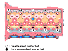
Install the cylinder head bolts with washers. Using the SST (09221-4A000), install and tighten the 10 cylinder head bolts in several passes in the specified sequence. Tightening torque: Step 1: 32.4 to 36 N·m Step 2: 90 to 95° Step 3: 90 to 95°
Do not reuse the cylinder head bolts.
Do not apply engine oil to the bolt threads to achieve the correct tightening torque.
Remove any sealant that squeezes out within 5 minutes after installing the cylinder head bolts.
Do not start the engine or perform a pressure test within 30 minutes after installing the cylinder head bolts.
Be careful not to change the installed position of the pre-assembled washer bolts and the unassembled washer bolts.
When installing the washers from the unassembled washer bolts, the rounded edge and chamfer of the washers must face up.
Install the rear engine mount (A).
Tightening torque: 34.3 to 39 N·m
Install the oil control valve (OCV) (A).
Tightening torque: 9.8 ~ 11.8 N·m
?
Test yourself
A quick Hyundai Elantra AD quiz: every answer comes with an explanation and a link to the manual page.