Body Electrical System
Front Wiper Motor Repair Procedures
In this manual: Body Electrical System
22steps
~132min
4/5difficulty
Done 0 of 22
Removal
- Disconnect the negative (-) battery terminal.
- If necessary, release the wiper blade lock by pulling up, and remove the blade from the inner radius of the wiper arm.
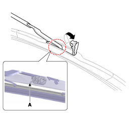
- Remove the upper hood cover. (Refer to Body - "Upper Cover Panel")
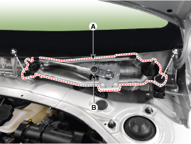
- Disconnect the windshield de-icer connector (B) after loosening the mounting bolts of the wiper motor assembly (A).
- While holding the wiper motor crank, remove the upper link (A).
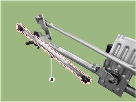
- While holding the wiper motor crank, remove the upper link (A).

- Before removing the wiper motor and linkage assembly, make sure the linkage has stopped at the automatic stop position.
- To accurately install the wiper motor crank, make sure the linkage is aligned with the crank in a straight line, and the angle of each link.
- Be careful not to bend the link.
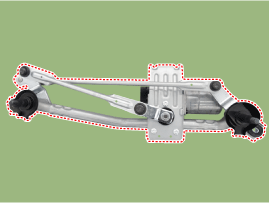
- Remove the lower link (A) from the wiper motor crank.
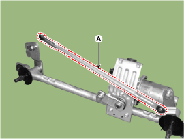
- To accurately install the wiper motor crank, make sure the linkage is aligned with the crank in a straight line, and the angle of each link.
- Be careful not to bend the link.
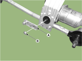
- Remove the crank (A) after loosening the nut (B).
- Remove the wiper motor (A) after loosening the bolts.
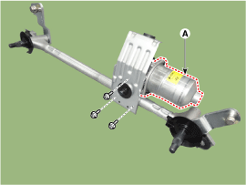
Installation
- Install the wiper motor.
- Install the crank.
Tightening torque: 14.7 ~ 19.6 N·m (1.5 ~ 2.0 kgf·m, 10.8 ~ 14.5 lbf·ft)
- To install the wiper motor crank, make sure that the linkage is aligned with the crank in a straight line and that the angle of each link is set correctly.
- Install the lower and upper links to the wiper motor crank.
- Install the wiper motor and linkage assembly, then connect the wiper motor connector.
Tightening torque: 7.0 ~ 11 N·m
- Install the hood upper cover.
- Install the windshield wiper arm and blade.
Tightening torque: 23.0 ~ 27 N·m (2.3 ~ 2.7 kgf·m, 16.6 ~ 19.5 lbf·ft)

- Turn the wiper motor to make sure it is in the park position. If necessary, adjust the wiper arm and blade.
- Install the wiper arm and blade in the specified position. A: Auto stop position (blade)

Inspection
- Disconnect the connector (A) from the wiper motor.

- Connect the positive (+) battery cable to terminal 3 and the negative (-) cable to terminal 5.
No Description 1 Ground 2 Parking 3 IGN 2 4 Low speed 5 High speed

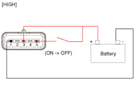
Inspection (with Multifunction Switch)
- The body wire harness system can quickly check faulty parts using the vehicle scan tool (GDS). The GDS provides the following information.
- Self-test: Diagnostic trouble code (DTC) check and display
- Data list: Check the status of system inputs/outputs.
- Forced operation: Check the operating status of the system
- Additional Functions: Other controls such as system option and zero point adjustment.
- Select the vehicle model and the system to check, then check the vehicle with the scan tool.
- After selecting BCM, select the module to check.
- Select "BCM" and "Instrument Panel Module (IPM)" to check the instrument panel module (IPM).
- Select the "Input/Output Monitor" menu to check the current status of the input/output data. The inputs/outputs for the sensors related to the Instrument Panel Module (IPM) can be checked.


Test yourself
A quick Hyundai Elantra AD quiz: every answer comes with an explanation and a link to the manual page.
Was this page helpful?