Drive Shaft and Axle
Front Hub / Steering Knuckle / Tone Wheel Repair Procedures
In this manual: Drive Shaft and Axle
31steps
~196min
5/5difficulty
2special tools
Done 0 of 31
Replacement
[4WD]- Loosen the wheel nuts slightly. Raise the vehicle and make sure it is securely supported.
- Remove the front wheel and tire (A) from the front hub.

Be careful not to damage the hub bolts when removing the front wheel and tire.
- Remove the brake caliper assembly. (Refer to Brake System - "Front Disc Brake")
- Loosen the drive shaft nut (A), then remove the brake disc by loosening the screw (B-3EA). Tightening torque A: 274.6 ~ 294 N·m (28.0 ~ 30.0 kgf·m, 202.5 ~ 217.1 ft-lbf) B: 4.9 ~ 5.9 N·m
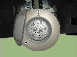
- Replace the front hub lock nut with a new one.
- After installing the lock nut, stake the lock nut using a chisel and hammer, as shown in the illustration below.
Staking Depth: 1.5 mm (0.591 in.)

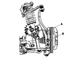
- Remove the wheel speed sensor by loosening the wheel speed sensor bracket bolt (A) and the wheel speed sensor mounting bolt (B).
Tightening torque: 6.9 ~ 10.8 N·m
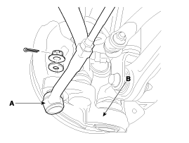
- Remove the tie rod end ball joint from the steering knuckle.
- Remove the cotter pin.
- Remove the castellated nut.
- Disconnect the ball joint (A) from the steering knuckle (B) using special service tool (09568-2J100).
Tightening torque: 88.3 ~ 108 N·m
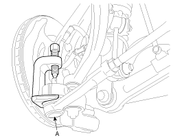
- Using special service tool (09568-2J100), remove the pinch bolt from the steering knuckle.
Tightening torque: 88.3 ~ 108 N·m
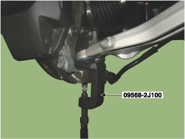
- Loosen the nut, then use special service tool (09568-2J100) to remove the lower arm from the steering knuckle.
Tightening torque: 88.3 ~ 108 N·m
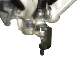
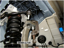
- Using special service tool (09568-2J100), separate the upper arm from the steering knuckle, then remove the steering knuckle assembly.
Tightening Torque: 78.5 ~ 88 N·m

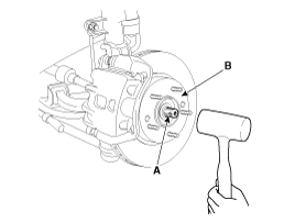
- Using a plastic hammer, disconnect the propeller shaft (A) from the axle hub (B).
- Loosen the hub mounting bolt and remove the hub assembly (B) from the steering knuckle (A).
Tightening torque: 88.3 ~ 108 N·m
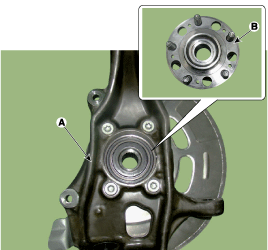
- Loosen the bolt and remove the dust cover (A).
Tightening torque: 6.9 ~ 10.8 N·m
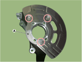
- Install in the reverse order of removal.
Use SST (09581-11000) when installing the brake caliper assembly. (Refer to Brake System - "Front Disc Brake") - Check the front alignment. (Refer to Suspension System - "Front Wheel Alignment")
- Loosen the wheel nuts slightly. Raise the vehicle and make sure it is securely supported.
- Remove the front wheel and tire (A) from the front hub.
Be careful not to damage the hub bolts when removing the front wheel and tire. - Remove the brake caliper assembly. (Refer to Brake System - "Front Disc Brake")
- Remove the brake disc by loosening the screw (A).
Tightening torque A: 4.9 ~ 5.9 N·m
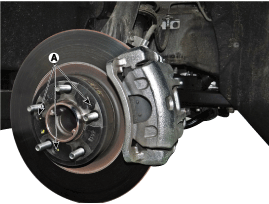
- Remove the wheel speed sensor by loosening the wheel speed sensor bracket bolt (A) and the wheel speed sensor mounting bolt (B).
: Tightening torque 6.9 ~ 10.8 N·m

- Remove the tie rod end ball joint from the steering knuckle.
- Remove the cotter pin.
- Remove the castellated nut.
- Disconnect the ball joint (A) from the steering knuckle (B) using special service tool (09568-2J100).
Apply a few drops of oil to the special service tool. (Loading contact part)
- Loosen the tensioner arm mounting bolt (A), then remove the tensioner arm (B).
Tightening torque: 88.3 ~ 108 N·m
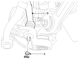
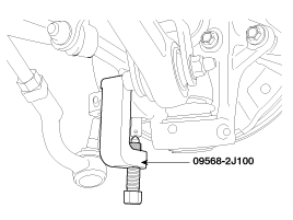
- Using special service tool (09568-2J100), remove the lower arm from the steering knuckle.
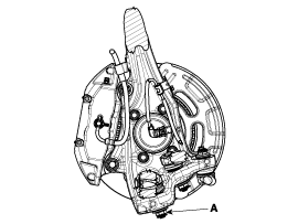
- Using special service tool (09568-2J100), separate the upper arm from the steering knuckle, then remove the steering knuckle assembly.
Tightening Torque: 78.5 ~ 88 N·m
- Loosen the hub mounting bolt and remove the hub assembly (B) from the steering knuckle (A).
Tightening torque: 88.3 ~ 108 N·m
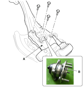
- Loosen the bolt and remove the dust cover (A).
Tightening torque: 6.9 ~ 10.8 N·m
- Install in the reverse order of removal.
Use SST (09581-11000) when installing the brake caliper assembly. (Refer to Brake System - "Front Disc Brake") - Check the front alignment. (Refer to Suspension System - "Front Wheel Alignment")
Inspection
- Check the hub for cracks and worn splines.
- Check the brake disc for scratches and damage.
- Check the joint for cracks.
- Check the bearing for cracks or damage.
Test yourself
A quick Hyundai Genesis DH quiz: every answer comes with an explanation and a link to the manual page.
Was this page helpful?