Body Electrical System
Instrument Cluster Repair Procedures
In this manual: Body Electrical System
24steps
~144min
4/5difficulty
Done 0 of 24
Removal
|

- Disconnect the negative (-) battery terminal.
- Remove the lower panel protective cover.
- Remove the driver's protective cover under the cap.
- Remove the upper cluster cover panel.
- Instrument Panel Upper Panel and Remove the front cluster panel.
- Loosen the mounting screw (4). Remove the instrument panel (A).
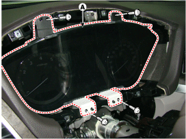
- Disconnect the instrument panel connector. Remove the instrument panel.
Installation
- Install the instrument cluster.
- Install the upper instrument panel cover and the front instrument panel cover.
- Install the upper cluster cover panel.
- Install the driver's protective cover under the cap.
- Install the emergency pad lower panel.
Inspection
- Checkpoint (Warning Lamp)
For malfunction conditions and normal operating conditions, refer to the Owner's Manual.
NO Reference Symbol Name Color Input Signal Signal Control Checkpoint 1 
Turn Signal (Left) Green CAN SJB
(Gateway)- Multifunction switch
- BCM
- SJB
- CAN failure
2 
Turn Signal (Right) Green CAN SJB
(Gateway)- Multifunction switch
- BCM
- SJB
- CAN failure
3 
Rear Lamp Green CAN SJB
(Gateway)- Multifunction switch
- BCM
- SJB
- CAN failure
4 
Fog Lamp Green CAN SJB
(Gateway)- Multifunction switch
- BCM
- SJB
- CAN failure
5 
High Beam Blue CAN SJB
(Gateway)- Multifunction switch
- BCM
- SJB
- CAN failure
6 
Warning Yellow MAY
+
Hard WiredBSD - BSD System
- CAN failure
PSB - PSB system
- SJB
- CAN failure
SCC
ESCA. SCC System B. AEB System C. LDWS System D. AGLS system E. TPMS System F. HSWS system - CAN failure
Low Washer - Washer Fluid Level Sensor
- Wiring Fault
Digital Input Service Reminder Indicator 7 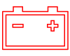
Battery Charge Red Hard Wired Generator - Generator
- Wiring Fault
- Battery
8 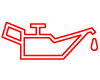
Oil Pressure Red Hard Wired ECM - Oil pressure sensor
- Wiring Fault
- ECM
- CAN failure
9 
Check Engine Yellow CAN ECM - ECM
- CAN failure
10 
Immobilizer Yellow MAY
+
Hard WiredSJB
(Gateway)- SMK system
- SJB
- CAN failure
- Hard Wired
11 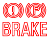
Parking Brake
Brake Fluid
EBD
EPB
Executive Vice PresidentRed CAN SJB
(Gateway)- IGPM
- DC system
- EPB System
- CAN failure
- Parking Brake Switch
- Brake lever sensor
EBD EPB 12 
ABS Yellow CAN ABS - DC system
- CAN failure
13 
ESC Yellow CAN TCS - DC system
- CAN failure
14 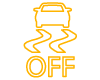
ESC OFF Yellow CAN TCS - DC system
- CAN failure
15 
EPB Yellow CAN EPB - EPB System
- CAN failure
16 
Auto Hold White CAN VDC - DC system
- CAN failure
Yellow Green 17 
Seat belt Red CAN SJB
(Gateway)- SJB
- CAN failure
18 
Air Bag Red CAN SRSCM - SRSCM System
- CAN failure
19 
EPS (MDPS) Red CAN MDPS - Single MDPS system
- MDPS Motor
- CAN failure
20 
SCP Yellow CAN SCP - TPMS System
- TPMS ??
- CAN failure
21 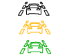
LDWS Green CAN LDWS - LDWS System
- CAN failure
Yellow White 22 
4WD Yellow CAN 4WD - AWD ECU
- CAN failure
23 
Fuel Warning Yellow Direct
(Micom)Fuel segment - Fuel segment failure
- Wiring Fault
24 
Door Open Red CAN SJB
(Gateway)- SJB
- CAN failure
- Door Sensor/Switch
25 
Liftgate open Yellow CAN SJB
(Gateway)- SJB
- CAN failure
- Trunk module
26 
ECO Green CAN ECO Mode - Drive Mode Switch
- ECU System
- TCU System
27 
SPORT Yellow CAN SPORT Mode - Drive Mode Switch
- ECU System
- TCU System
28 
SNOW White CAN SNOW MODE - Drive Mode Switch
- ECU System
- TCU System
29 
AEB Yellow CAN AEB Error - SCC System
- CAN failure
- TR Switch (Sensor)
NO Name Input Signal Signal Control
(Unit/Sensor)Checkpoint 1 Speedometer C-CAN TCU 1) CAN Line Fault 3 Tachometer C-CAN Emergency Call 1) CAN Line Fault 4 Engine Coolant Temperature C-CAN Emergency Call 1) CAN Line Fault 5 Fuel Hard Wire Fuel Grinder 1) Fuel Sender Malfunction 2) Wiring Fault 6 Shift Lever Indicator C-CAN TCU 1) CAN Line Fault 7 Compass MM-CAN HU 1) CAN Line Fault 8 Outside Temperature C-CAN DATC 1) CAN Line Fault - Other Cluster Checklist
- USM (User Setting Mode) USM Setting Procedure (Mode: 24) The setting can be changed using the buttons on the steering wheel switch. Items include Seat Sync Entry/Exit, Auto Door Lock, Auto Door Lock Release, Headlamp Following, Welcome Light, Welcome Sound, Triple Turn Signal, Auto Reset of Average Fuel Consumption, HUD Height, Brightness, and Content Settings. These items can be set and changed.
- It allows quick diagnosis of CLU defects using GDS. GDS can forcibly operate actuators, monitor input/output values, and perform self-diagnosis.
- Select the model and "BCM".
- Select "Cluster Module" for inspection.
- Select "Input/Output Control" to check the current data of the instrument cluster.
- To forcibly check the operation of each module, select "Actuation Test".
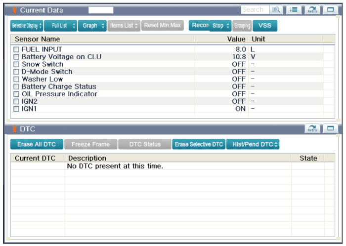
- Connect the GDS cable to the data link connector on the lower panel of the driver's side airbag, then turn on the GDS power.
- Select the model and "BCM".
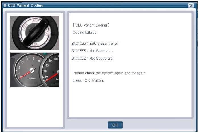
- Select Variant Coding mode to perform.
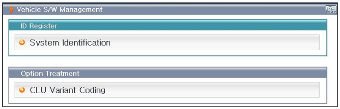
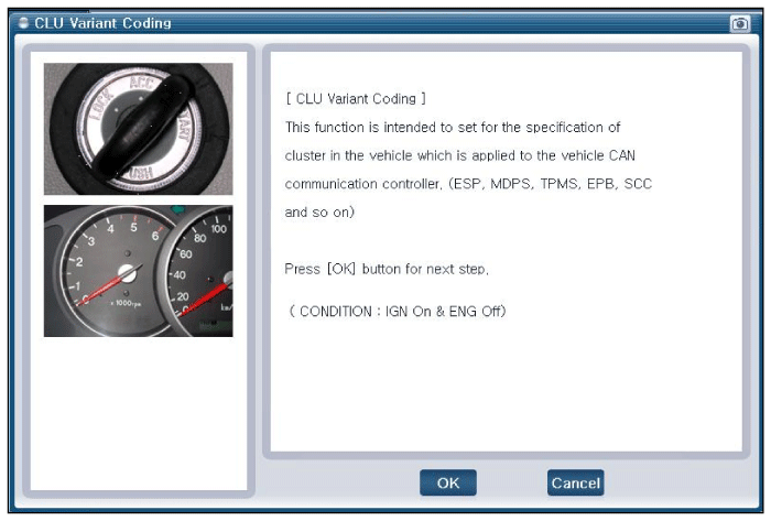
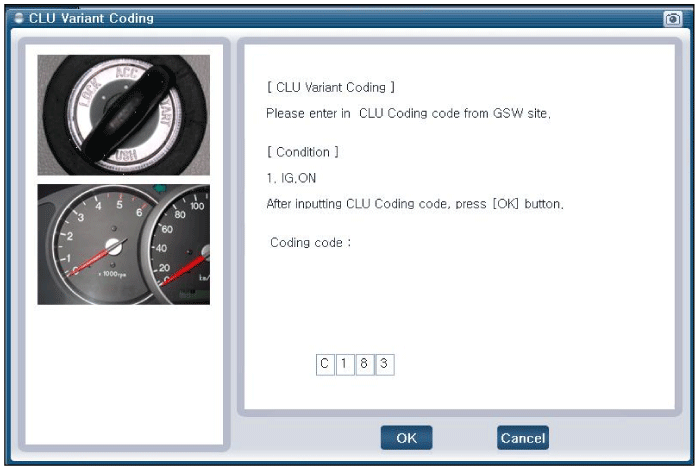
- If trouble codes occur while performing variant coding, retry CLU variant coding after checking the CLU installation status.
Test yourself
A quick Hyundai Genesis DH quiz: every answer comes with an explanation and a link to the manual page.
Was this page helpful?