Body Electrical System
Description and Operation of Instrument Cluster
In this manual: Body Electrical System
4steps
~24min
2/5difficulty
Done 0 of 4
Description
Communication Network Diagram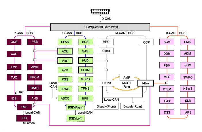
| Abbreviation | Description |
| AAF | Active Air Flap |
| ACU | Airbag Control Unit |
| ADM | Assist Door Module |
| AHD | Active Hood System |
| AMP | Amplifier |
| ARS | Armrest Switch |
| ASCC | Advanced Smart Cruise Control |
| AVM | Around View Monitor |
| All-wheel drive | All-Wheel Drive |
| B_CAN | Body Controller Network |
| BCM | Body Control Module |
| BSD | Blind Spot Detection |
| C_CAN | Chassis Controller Area Network |
| CPK | Center Control Panel |
| KLUM | Cluster Module |
| DATC | Dual Automatic Temperature Control |
| DDM | Driver door module |
| Display | Display Monitor |
| DSS | Driver Seat Switch |
| ECS | Electronic Control Suspension |
| Emergency Call | Engine Control System |
| EPB | Electronic Parking Brake (EPB) |
| EVP | Electric Vacuum Pump (EVP) |
| FPCM | Fuel Pump Control Module |
| ea. | Head unit |
| HSWS | Tactile Steering Warning |
| HUD | Projection Display |
| I-BOX | Telematics System |
| IBR | Integrated Dynamic Brake |
| LDWS | Lane Departure Warning System |
| M_CAN | Multimedia Controller Network |
| MDPS | Motor Driven Power Steering |
| MFS | Multifunction switch |
| ORV | Passenger Sensing System |
| P_CAN | Power Train Controller Area Network |
| PGS | Park Assist System |
| PSB | Pre-Safe Belt |
| PSM | Power Seat Module |
| PTLM | Power Liftgate Module |
| RKR | Rear Remote Control |
| CAC | Steering Wheel Angle Sensor |
| SKM | Steering Column Module |
| SJB | Smart Junction Box |
| SLB | Lumbar Seat |
| SMK | Smart Key Unit |
| SPAS | Smart Parking Assist System (SPAS) |
| SWRC | Steering Wheel Remote Control |
| TCU | Transmission Control Unit |
| SCP | Tire Pressure Monitoring System |
| VDC | Vehicle Dynamic Control |
|

- High-Speed CAN Communication (C-CAN)
A. User function: Auto seat linked to walk-away locking/unlocking, welcome light B. LDWS: Lane Departure Warning System C. SPAS: Smart Parking Assist System - Low-speed CAN communication (M-CAN)
A. AV: Audio/Video Multimedia Information Display B. TBT: Turn-by-Turn Navigation Information Display - Various Alarm Source Control: Various warning alarms and sound effects are reproduced through external speakers connected to the instrument cluster.
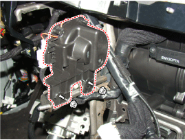
Sound Description and Function (CAN Data Receiver) Welcome Welcome (Key Removed and Door Open/Closed, Checked by BCM) Goodbye Goodbye (Cluster) Open Door Warning Key reminder (BCM): vehicle speed 5 km/h or less & IGN switch in ACC or IGN or engine start position, and when vehicle speed is below 5 km/h or the driver's door is open Unfastened Seat Belt Warning Driver Unfastened Seat Belt Warning (BCM) PAS System Warning PAS Sensor Malfunction Warning (BCM) R Gear PAS Warning When Shifting to R Gear (BCM and SPAS) Parking Brake Parking Brake Warning (BCM) Start Button SSB Button Warning (SMK) Rheostat Light Information Rheostat Warning When Maximum or Minimum Level Is Selected (Cluster) Smart Key Transmission Smart Key Not Present Warning (SMK) ? Smart Key Warning (SMK) Smart Cruise Changeover from Normal Cruise to Smart Cruise (SCC) Smart Cruise Driving Information Smart Cruise (SCC) Function Cancellation Normal Cruise Changeover from Smart Cruise to Normal Cruise (SCC) Turn Signal Lamp (Check Mark) Turn Signal Lamp Warning (BCM) Turn Signal Lamp (Tock) Turn Signal Lamp Warning (BCM) Smart Key Low Battery Voltage Warning When Driver Presses SSB Button with Smart Key Low Battery (SMK) EPB Warning Warning When Changing from Auto Hold to EPB Lock (EPB) Coolant Temperature Warning When Engine Temperature Is Above 120 °C - User Setting Mode (USM): The setting can be changed using the tactile switch menu and the CW, CCW, OK buttons (or the UP, DOWN, LEFT, RIGHT and OK buttons on the universal switch). There are a total of 24 items (e.g., In/Out Seat Sync, Steering Wheel Sync, Auto Door Lock, Auto Door Unlock, Headlamp Follow-Me, Welcome Light, Welcome Sound, Triple Turn Signal, Automatic Average Fuel Consumption Reset, HUD Height, Brightness and Content Settings) that can be individually customized. The signal flow during setting is as follows.
- USM settings are configured and transmitted to the BCM.
- The BCM transmits the settings via B-CAN to the corresponding modules.
- The module completes the setting and transmits the changed setting to the BCM.
- The BCM transmits the final settings via C-CAN to the cluster.
Test yourself
A quick Hyundai Genesis DH quiz: every answer comes with an explanation and a link to the manual page.
Was this page helpful?