Engine Control System/Fuel System
Troubleshooting
In this manual: Engine Control System/Fuel System
69steps
~414min
4/5difficulty
Done 0 of 69
Basic Troubleshooting Procedures
Basic Troubleshooting Procedure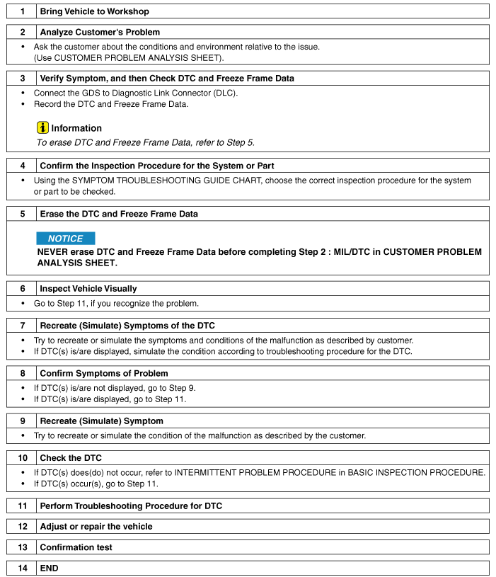
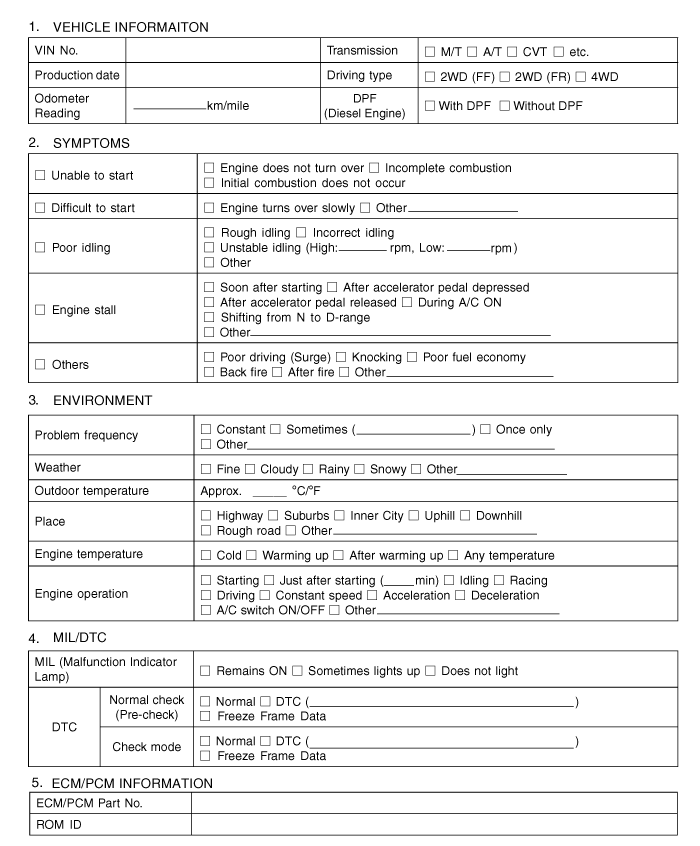
Electronic Component Resistance Measurement Conditions
Resistance measured at high temperature after starting the vehicle may be high or low. Therefore, all resistances should be measured at ambient temperature (20 °C, 68°F), unless otherwise specified.
|
From a troubleshooting standpoint, the most difficult case is when the symptom causing the problem cannot be reproduced during testing. For example, the symptom appears when the vehicle is cold but does not appear when it is warm. In this case, the service technician must understand the Customer Problem Analysis Sheet and reproduce the environment and conditions in which the vehicle showed the symptom.
- Clear the Diagnostic Trouble Code (DTC).
- Inspect the connector and check the terminals for poor connections, loose wires, and bent, broken, or corroded contacts. Also check that the connectors are securely connected.
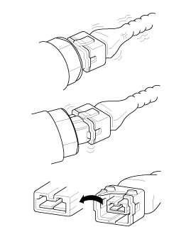
- Gently move the connector and wiring harness up and down or side to side.
- Repair or replace the faulty component.
- Make sure the symptom no longer occurs after performing a road test.
- Sensors and Actuators: Gently shake sensors, actuators, or relays by hand.
Strong vibration may damage sensors, actuators or relays.
- Connectors and Harness: Gently move the connector and wiring harness up and down or side to side.
- Heat the components suspected of causing the malfunction using a hair dryer or other heat source.
- DO NOT heat the components to the point where they may be damaged.
- DO NOT heat the ECM directly.
- Using a heat gun or other device, heat the components suspected of causing the malfunction.
DO NOT spray water directly into the engine compartment or onto electrical components. - Turn on all electrical systems to simulate excessive electrical loads (radio, fans, lights, rear window defogger, etc.).
- Connector Handling
A. When disconnecting connectors, pull on the connector, not the wiring harness. 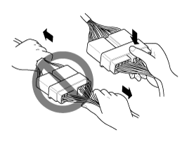
B. When disconnecting a connector with a lock, press or pull the locking lever. 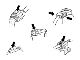
C. When connecting connectors, check for a click to make sure the connectors are securely engaged. 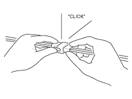
D. When using a tester to check continuity or measure voltage, always insert the test probe from the wiring harness side. 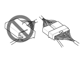
E. Check waterproof connector terminals from the connector side. Waterproof connectors cannot be accessed from the wire harness side. 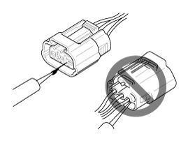

- Use a thin wire to avoid damaging the terminal.
- Do not damage the terminal when inserting the tester wire.
- Connector Checkpoints
A. With the connector connected: While holding the connector, check the connection condition and locking efficiency. B. With the connector disconnected: Check for a missing terminal, crimped terminal, or broken wire core by gently pulling the wiring harness. Visually check for rust, contamination, deformation, and sagging. C. Check terminal tightness: Insert a spare male terminal into the female terminal, then check the terminal tightness condition. D. Gently pull on each individual wire to confirm that each wire is secured in the terminal. 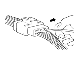
- Connector Terminal Repair Method
A. Clean the contact points using an air gun and/or a cotton cloth.
Never use sandpaper to polish contact points, as this may damage the contact point.B. If contact pressure is abnormal, replace the female terminal. - Before removing the wire harness, check the position and clamping of the wire harness to restore it correctly.
- Check whether the wiring harness is twisted, sagging, or loose.
- Check that the wire harness is not exposed to excessive temperature.
- Check that the wire harness does not rotate, move or vibrate against sharp edges of components.
- Check the connection between the wire harness and any installed part.
- Check whether the wiring harness covering is damaged.
- Open Circuit Procedures
A. Continuity Check
If an open circuit occurs (as shown in [FIG. 1]), it can be located by performing Step 2 (Continuity Check Method) or Step 3 (Voltage Check Method), as shown below.B. Voltage Check 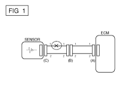
- Continuity Check Method
Specification (resistance) 1 Ω or less > Normal circuit; 1 MΩ or more > Open circuit
When measuring resistance, gently move the wiring harness up and down or side to side.A. Disconnect connectors (A) and (C), and measure the resistance between connectors (A) and (C), as shown in [FIG. 2]. If the measured resistance of lines 1 and 2 is above 1 MΩ and 1 Ω respectively in [FIG. 2], line 1 is open (line 2 is normal). To find the exact break point, check the sub-line of line 1 (next step). 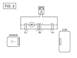
B. Disconnect connector (B) and measure the resistance between connector (C) and (B1), and between (B2) and (A), as shown in [FIG. 3]. If the measured resistance between connector (C) and (B1) is 1 MΩ or higher, and the resistance between (B2) and (A) is 1 Ω or lower, line 1 of connector (C) and line 1 of connector (B1) are open circuits. 
- Voltage Check Method
A. With each connector still connected, measure the voltage between chassis ground and terminal 1 of each connector (A), (B) and (C), as shown in [FIG. 4]. The measured voltage of each connector is 5 V, 5 V and 0 V, respectively. Therefore, the circuit is open between connectors (C) and (B). 
- Short to Ground Check Method
If a short to ground occurs, as shown in [FIG. 5], the breakpoint can be located by performing Step 2 (Continuity Check Method with chassis ground), as shown below.A. Continuity Check with Chassis Ground 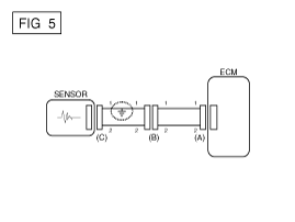
- Continuity Check Method (with Chassis Ground)
Specification (resistance) 1 Ω or less > Short to ground; 1 MΩ or more > Normal circuit
Gently shake the wiring harness up and down or side to side while measuring resistance.A. Disconnect connectors (A) and (C), and measure the resistance between connector (A) and chassis ground, as shown in [FIG. 6]. In this example, the measured resistance of lines 1 and 2 is below 1 Ω and above 1 MΩ respectively. Specifically, line 1 is shorted to ground (line 2 is normal). To find the exact break point, check the sub-line of line 1 as described in the next step. 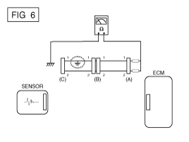
B. Disconnect connector (B) and measure the resistance between connector (A) and chassis ground, and between (B1) and chassis ground, as shown in [FIG. 7]. The measured resistance between connector (B1) and chassis ground is 1 Ω or less. The short to ground is between terminal 1 of connector (C) and terminal 1 of connector (B1). 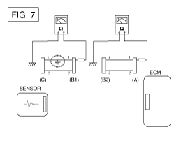
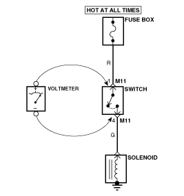
- Connect the positive voltmeter lead to the wire end (or connector or switch side) closest to the battery.
- Connect the negative lead to the other end of the wire (or the other side of the connector or switch).
- Operate the circuit.
- The voltmeter will show the voltage difference between two points. A difference or drop of more than 0.1 V (50 mV in a 5 V circuit) may indicate a problem. Check the circuit for dirt and loose connections.
? Simulate heat
? Simulate water spray
? Simulate electrical load
Connector Inspection Procedure
Wiring Harness Inspection Procedure
Electrical Circuit Inspection Procedure
? Check for open circuit
? Check for short circuit
? Voltage drop test
This test checks the voltage drop across a wire, connection, or switch.
Symptom Troubleshooting Table
| Main Symptom | Diagnostic Procedure | Also check |
| Cannot Start (Engine does not crank) |
|
|
| Cannot Start (Incomplete combustion) |
|
|
| Hard to Start |
|
|
| Poor Idling (Rough, unstable or incorrect idle) |
|
|
| Engine Stalls |
|
|
| Poor Driveability (Surging) |
|
|
| Knock |
|
|
| Poor Fuel Economy |
|
|
| Hard to Refuel (Overflow during refueling) |
|
|
Test yourself
A quick Hyundai Genesis DH quiz: every answer comes with an explanation and a link to the manual page.
Was this page helpful?