Remove the cylinder head cover. (Refer to Cylinder Head - "Cylinder Head Cover")
Remove the vacuum pump. (Refer to Cylinder Head Assembly - "Vacuum Pump")
Remove the timing chain. (Refer to Valve Timing System - Timing Chain)
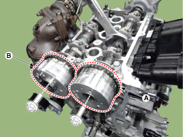
Remove the intake (A) and exhaust (B) CVVTs.
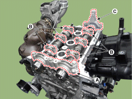
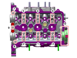
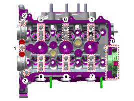
Remove the front camshaft bearing cap (A), the intermediate camshaft bearing cap (B), and the rear camshaft bearing cap (C) in the order shown.
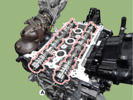
Remove the camshaft (A).
Inspection
Camshaft
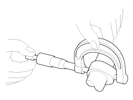
Inspect the cam lobes. Using a micrometer, measure the cam lobe height. CAM LOBE HEIGHT Intake: 41.79824 mm (1.6456 in.) Exhaust: 41.57000 mm (1.6366 in.)If the cam lobe height is less than the standard value, replace the camshaft.
Inspect the camshaft journal oil clearance.
Clean the bearing caps and the camshaft journals.
Install the camshafts on the cylinder head.
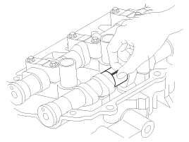
Place a strip of Plastigage across each camshaft journal.
Install the front camshaft bearing cap (A), the intermediate camshaft bearing cap (B), and the rear camshaft bearing cap (C) using the following procedure, tightening to the specified torque. Tightening torque: Step 1 A: 9.8 N·m B: 5.9 N·m Step 2 A: 18.6 - 23 N·m B: 11.8 - 13.7 N·m C: 11.8 - 13.7 N·m
Remove the bearing caps.
Measure the Plastigage at its widest point. CAMSHAFT JOURNAL OIL CLEARANCE SPECIFICATION: 0.027 - 0.057 mm (0.0010 - 0.0022 in.) Exhaust: 0.027 - 0.057 mm (0.0010 - 0.0022 in.) CAMSHAFT JOURNAL OUTER DIAMETER Intake/Exhaust No. 1: 36.464 - 36.478 mm (1.4356 - 1.4361 in.) Intake/Exhaust No. 2 - 5: 20.964 - 20.978 mm (0.8254 - 0.8259 in.) BEARING HOUSING INNER DIAMETER Intake/Exhaust No. 1: 36.505 - 36.521 mm (1.4372 - 1.4378 in.) Intake/Exhaust No. 2 - 5: 21.005 - 21.021 mm (0.8270 - 0.8276 in.) If the oil clearance is greater than the maximum value, replace the camshaft. If necessary, replace the cylinder head.
Completely remove the Plastigage.
Remove the camshaft.
Inspect the camshaft end play.
Install the camshaft (A).
Install the front camshaft bearing cap (A), the intermediate camshaft bearing cap (B), and the rear camshaft bearing cap (C) using the following procedure, tightening to the specified torque. Tightening torque: Step 1 A: 9.8 N·m B: 5.9 N·m Step 2 A: 18.6 - 23 N·m B: 11.8 - 13.7 N·m C: 11.8 - 13.7 N·m
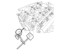
Using a dial indicator, measure the camshaft end play by moving the camshaft forward and backward. CAMSHAFT END PLAY SPECIFICATION: 0.1 - 0.2 mm (0.0039 - 0.0078 in.) Exhaust: 0.1 - 0.2 mm (0.0039 - 0.0078 in.)If the end play is greater than the maximum value, replace the camshaft. If necessary, replace the cylinder head.
Remove the camshafts.
Inspect the CVVT assembly.
Secure the camshaft in a vise. Be careful not to damage the camshaft lobes and journals.
Make sure the CVVT is locked by attempting to rotate it clockwise and counterclockwise. It must not rotate.
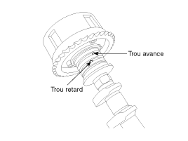
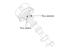
Intake CVVT: Cover one of the two holes in the camshaft journal with tape. Exhaust CVVT: Cover one of the two retard holes in the camshaft journal with tape. [Specification][Exhaust]
Intake CVVT: Apply approximately 150 kPa (1.5 kgf/cm², 21 psi) of compressed air to the uncovered advance hole to unlock the CVVT. Exhaust CVVT: Apply approximately 150 kPa (1.5 kgf/cm², 21 psi) of compressed air to the uncovered retard hole to unlock the CVVT.
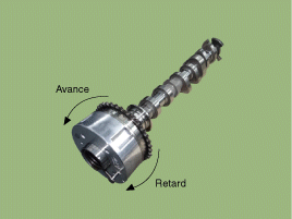
Intake CVVT: While applying compressed air, rotate the CVVT in the advance direction (counterclockwise) within the phase range and make sure the CVVT rotates smoothly. Exhaust CVVT: While applying compressed air, rotate the CVVT in the retard direction (clockwise) and make sure the CVVT rotates smoothly.CVVT PHASE RANGE SPECIFICATION: Intake: 25° (from maximum retard position to maximum advance position) Exhaust: 20° (from maximum advance position to maximum retard position)
Intake CVVT: Rotate the CVVT to the maximum retard position (clockwise), then make sure the CVVT is locked. Exhaust CVVT: Rotate the CVVT to the maximum advance position (counterclockwise), then make sure the CVVT is locked.
Install the front camshaft bearing cap (A), the intermediate camshaft bearing cap (B), and the rear camshaft bearing cap (C) in the order shown. Tightening torque: Step 1 A: 9.8 N·m B: 5.9 N·m Step 2 A: 18.6 - 23 N·m B: 11.8 - 13.7 N·m C: 11.8 - 13.7 N·m
Install the intake (A) and exhaust (B) CVVTs.
Tightening torque: 63.7 ~ 74 N·m
Install the remaining parts in the reverse order of removal.
?
Test yourself
A quick Hyundai i20 quiz: every answer comes with an explanation and a link to the manual page.