Engine Mechanical System
CYLINDER HEAD Repair Procedures
In this manual: Engine Mechanical System
30steps
~205min
5/5difficulty
5special tools
Done 0 of 30
DEPOSIT
- Remove the engine cover. (Refer to Engine and Transaxle - "Engine Cover")
- Remove the engine undercover. (Refer to Engine and Transaxle Assembly - "Engine Undercover")
- Drain the engine coolant. (Refer to Cooling System - "Cooling")
- Remove the intake manifold. (Refer to Exhaust and Intake System - "Intake Manifold")
- Remove the exhaust manifold. (Refer to Intake and Exhaust System - "Turbocharger and Exhaust Manifold")
- Remove the water temperature control unit. (Refer to Cooling System - "Water Temperature Control")
- Remove the vacuum pump. (Refer to Cylinder Head Assembly - "Vacuum Pump")
- Remove the cylinder head cover. (Refer to Cylinder Head - "Cylinder Head Cover")
- Remove the fuel feed pipe. (Refer to Engine Control/Fuel System - "Fuel Hose")
- Remove the timing chain. (Refer to Valve Timing System - Timing Chain)
- Remove the camshaft. (Refer to Cylinder Head - "CVVT and Camshaft")
- Remove the intake and exhaust oil control valves (OCV). (Refer to Engine Control System/Fuel System - "Engine Oil Control Valve CVVT (OCV)").
- Remove the camshaft position sensor (CMPS). (Refer to Fuel System/Engine Control - "Camshaft Position Sensor (CMPS)").
- Remove the cylinder head.
- Using a square socket, loosen the 8 cylinder head bolts evenly and in several passes, in the sequence shown. Remove the 8 cylinder head bolts and plate washers.

- Lift the cylinder head (A) off the guide pins on the cylinder block and place it on wooden blocks and a workbench.
- Remove the cylinder head gasket (B).

- Using a square socket, loosen the 8 cylinder head bolts evenly and in several passes, in the sequence shown. Remove the 8 cylinder head bolts and plate washers.
DISASSEMBLY
- Remove the MLA (mechanical lash adjuster) (A).
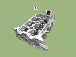
- Remove the valves.
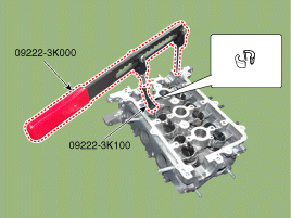
- Using SST (09222-3K000, 09222-3K100), compress the valve spring and remove the valve cotter.
- Remove the spring retainer.
- Remove the valve spring.
- Remove the valve.
- Using special service tool (09222-29000), remove the valve stem seal.

- Using SST (09222-3K000, 09222-3K100), compress the valve spring and remove the valve cotter.
Inspection
CYLINDER HEAD COVER- Inspect the cylinder head flatness. Using a straightedge and feeler gauge, measure the mating surfaces of the cylinder block and manifolds to check for distortion. Cylinder head gasket surface flatness Standard: less than 0.05 mm (0.0020 in.) Limit: less than 0.02 mm (0.0008 in.)/100 x 100 Manifold gasket surface flatness Standard: less than 0.1 mm (0.0039 in.)

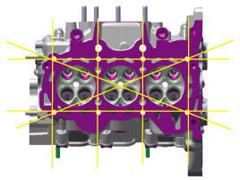
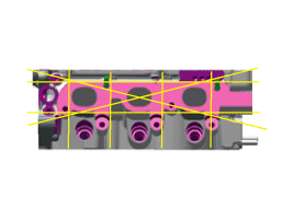
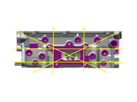
- Inspect for cracks. Check the combustion chambers, intake and exhaust ports and the cylinder block surface for cracks. If cracked, replace the cylinder head.
- Inspect the valve stems and valve guides.
- Using a caliper gauge, measure the inside diameter of the valve guide. Valve guide inside diameter Intake/Exhaust: 5.500 - 5.512 mm (0.2165 - 0.2170 in.)

- Using a micrometer, measure the diameter of the valve stem. Valve stem outside diameter Intake: 5.465 - 5.480 mm (0.2151 - 0.2157 in.) Exhaust: 5.448 - 5.460 mm (0.2144 - 0.2149 in.)
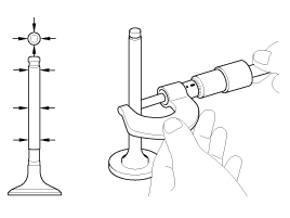
- Subtract the valve stem diameter from the valve guide inside diameter. Stem-to-guide clearance Intake: 0.020 - 0.047 mm (0.00078 - 0.00185 in.) Exhaust: 0.040 - 0.064 mm (0.00157 - 0.00251 in.)
- Using a caliper gauge, measure the inside diameter of the valve guide. Valve guide inside diameter Intake/Exhaust: 5.500 - 5.512 mm (0.2165 - 0.2170 in.)
- Inspect the valves.
- Make sure the valve face is ground at the correct angle to the contact surface.
Valve face angle: Intake/Exhaust: 45.25° - 45.75°
- Make sure the valve face is not damaged. If the valve face is worn, replace the valve.
- Check the valve head margin thickness. If the margin thickness is less than the minimum value, replace the valve.
Margin thickness Intake: 1.5 mm (0.0590 in.) Exhaust: 1.75 mm (0.0688 in.)

- Check the valve length.
Overall length Intake: 92.85 mm (3.6555 in.) Exhaust: 93.37 mm (3.6759 in.)
- Check the valve stem end surface for damage. If the valve stem end is worn, replace the valve.
- Make sure the valve face is ground at the correct angle to the contact surface.
- Inspect the valve seats.
- Check the valve seat for overheating or contact with the valve face. If the valve seat is worn, replace the cylinder head.
- Before reconditioning the seat, check the valve guide for wear. If the valve guide is worn, replace the cylinder head.
- Recondition the valve seat using a valve seat reamer or valve seat cutter. The valve seat contact width must meet the specifications and be centered on the valve face. Valve seat contact width: Intake: 0.85 - 1.15 mm (0.0334 - 0.0452 in.) Exhaust: 1.35 - 1.65 mm (0.0531 - 0.0649 in.) Valve seat angle: Intake/Exhaust: 44.75° - 45.10°
- Inspect the valve springs.
- Using a steel square, measure the valve spring squareness.
- Using a caliper gauge, measure the free length of the valve spring. Valve spring free length: 47.9 mm (1.8858 in.) Squareness: 1.5° (MAX.)
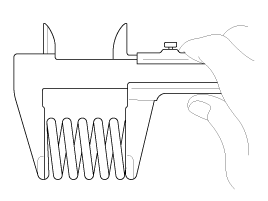
- Inspect the MLA. Using a micrometer, measure the outside diameter of the MLA. MLA outside diameter Intake/Exhaust: 27.964 - 27.980 mm (1.1010 - 1.1016 in.)
MLA outside diameter Intake/Exhaust: 27.964 - 27.980 mm (1.1010 - 1.1016 in.)
- Using a caliper gauge, measure the inside diameter of the MLA tappet bore in the cylinder head. Tappet bore inside diameter Intake/Exhaust: 28.000 - 28.025 mm (1.1024 - 1.1033 in.)
- Subtract the MLA outside diameter from the tappet bore inside diameter. MLA-to-bore clearance [Limit] Intake/Exhaust: 0.020 - 0.061 mm (0.0008 - 0.0024 in.)
Installation
- Install the valves.
- Using special service tool (09222-1S100), install a new valve stem seal.
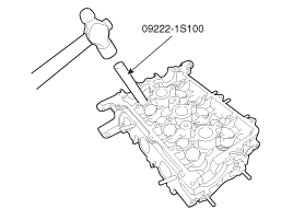
- Install the valve, valve spring and spring retainer.
- Using SST (09222-3K000, 09222-3K100), compress the spring and install the valve cotters. After installing the valves, make sure the cotters are seated correctly before releasing the valve spring compression.
- Lightly tap the end of each valve stem two or three times with a wooden mallet to make sure the valve and retainer are installed correctly.
- Using special service tool (09222-1S100), install a new valve stem seal.
- Install the MLA (mechanical lash adjuster) (A).
REMEDY
- Install the cylinder head gasket.
- Make sure there is no engine oil on the cylinder head gasket contact surface, cylinder block, timing chain lower cover, etc.
- Before installing the cylinder head gasket, apply liquid gasket to the top surface of the cylinder block and install the gasket within five minutes.
Bead width: 2.0 ~ 3.0 mm (0.08 ~ 0.12 in.)
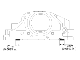
- Install the cylinder head gasket (A) on the cylinder block.

- After installing the cylinder head gasket on the cylinder block, apply liquid gasket to the top surface of the gasket and assemble the cylinder head within five minutes. Bead width: 2.0 ~ 3.0 mm (0.08 ~ 0.12 in.) Sealant: TB1217H or LOCTITE 5900H.

- Remove any excess sealant after assembling the cylinder head.
- Install the cylinder head assembly.
- Carefully place the cylinder head (A) in position, taking care not to damage the gasket.
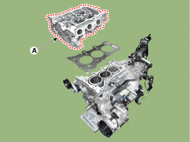
- Using SST 09221-4A000, tighten the cylinder head bolts and dome washers several times in the order shown. Torque: 12.7 ~ 16.7 N·m +90~95°+120~125°
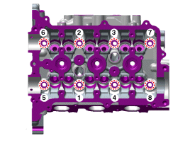
- Carefully place the cylinder head (A) in position, taking care not to damage the gasket.
- Install the remaining parts in the reverse order of removal.
Test yourself
A quick Hyundai i20 quiz: every answer comes with an explanation and a link to the manual page.
Was this page helpful?