Body Electrical System
Description and Operation
In this manual: Body Electrical System
5steps
~30min
2/5difficulty
Done 0 of 5
Description
GENERAL DESCRIPTION OF THE SYSTEM The system has the following features:- The driver interacts with the system using the one-step button to change the terminal and start the engine.
- Control of external relays to switch the ACC/ALL1/ALL2 terminals and STARTER without using a mechanical ignition switch.
- Steering column locking by the ESCL unit, checking vehicle status to ensure safe ESCL activation.
- Vehicle status indication by LEDs or explicit messages.
- Immobilizer function through AvG transponder communication between the key fob and the Start/Stop button.
- Redundant architecture for high system reliability
- Interface with the vehicle low-speed CAN communication network.
- Interface with the vehicle LIN communication network, depending on the platform.
- Steering column lock/unlock by ESCL.
- Switching of ACC/ALL1/ALL2 terminals.
- Control of the BAT (high side) line of the STARTER relay based on communication with the EMS ECU.
- Control of the immobilizer function.
- Control of the BES warning function.
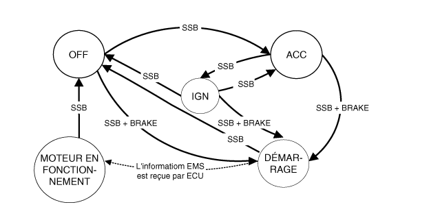
- Control of ignition and engine start/stop by sending a signal to the IPM.
- Status display by ON/OFF LED indicator (amber or blue).
| NO | Character indicator | Confirmation |
| 1 | Power indicator | Door open, tail lamps on, ACC, ignition on |
| 2 | Indicator lamp ON for 30 sec → Lamp OFF | Door closed, tail lamps off, ignition off |
| 3 | Indicator OFF | Remote LOCK, passive LOCK |
| 4 | Tail lamp dimmer on (illumination indicator) | |
ON/OFF Indicator Status by Ignition Key Position
| NO | Ignition conditions | Power button indicator status |
| 1 | Ignition off | LED is off |
| 2 | ALL ACC | Yellow LED on |
| 3 | IGNITION ON (engine off) | Blue LED on |
| 4 | Starting | Hold LED status before starting |
| 5 | ENGINE RUNNING | LED is off |
Operation for Each Start Button Function
- Power on / ignition on
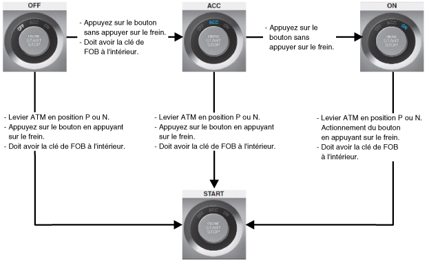
- The power supply undergoes the following changes: OFF → ACC → IGN → OFF by pressing the button without pressing the brake (or pressing the brake) inside the vehicle with the key fob (however, repeat ACC↔IGN when speed is not in P. Switching to OFF is not possible.)
- Start is initiated by pressing the button while pressing the brake in the P/N position with the key fob.
- Power off / ignition off
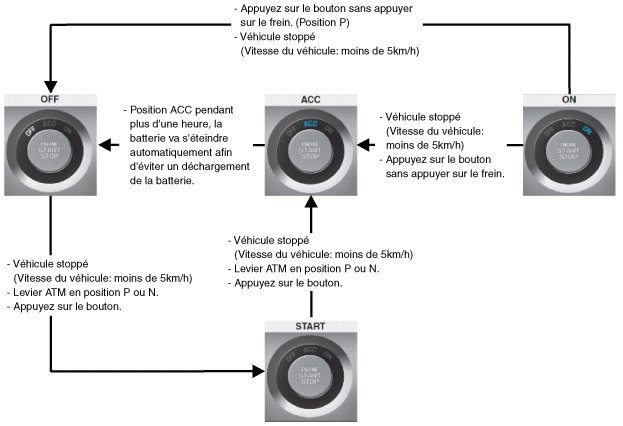
- Ignition off is possible when the vehicle is stationary. (Ignition off is possible in any Selector lever position.)
- The lever will be held in N, and to park, press the lever release button after turning the ignition to OFF.
- How to forcibly turn off the ignition and restart the engine while driving
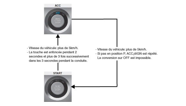
- This is a method of forcibly stopping the vehicle in case of fuel leakage or an emergency (for example, a malfunctioning accelerator pedal return).
- The engine stops and returns to the ACC state when the button is pressed for 2 seconds or more, 3 times successfully within 3 seconds, while driving. Restart is available within the following 30 seconds regardless of the key fob. The power supply goes through the following transitions: OFF → ACC → IGN → OFF by pressing the button without pressing the brake (or with the brake pressed) inside the vehicle with the key fob. (However, when not in P, ACC↔IGN repeats. Conversion to OFF is not possible.)
- Brake switch input has a 0.5 second delay function. Starting is possible with the brake pedal pressed 0.5 seconds after pressing the start button with the engine off.
- The start button indicator (LED) illuminates according to the power supply status.
- Power off: LED off
- ACC power supply status: yellow LED illuminated
- Power on: blue LED illuminated
- During start: the previous LED remains illuminated until start
- Initial ON state: LED OFF
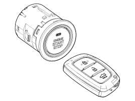
- When brake input is not made (AT specification), transition to START when SSB is pressed for more than 10 seconds in the ACC state.
- If there is a communication problem between EMS and CAN (mainly unable to determine EMS status), transition to MOTORCYCLE state from START based on input from the trusted platform module.
- In case of absence of two SSB input lines, power on and off is available by pressing SSB twice within 10 seconds (SSB LIMP HOME PRESS). The buzzer sounds when the button is pressed the first time. Power cycle is available, and the buzzer stops when the button is pressed twice within ten seconds.

- On/Off button (SSB) control,
- Immobilizer communication (with engine control unit to activate immobilizer),
- Authentication server (transponder validity and, in case of authentication, passive key fob option SMK),
- system integrity check,
- system diagnostics,
- Message display/buzzer control
- Terminal control relay
- Check vehicle speed received from the ABS/ESP sensor ECU.
- SSB LED control (on, off)
- Control of the base station located in the SSB via direct serial interface.
- System consistency check to diagnose SMK failure and enter driving recovery mode.
- Provision of vehicle speed information
- On/Off button (SSB) control
- Electric starter control
- Activation of OFF, ACC, ON and START power modes by switching to the corresponding terminals
- Starting the Engine
- Turning Off the Engine
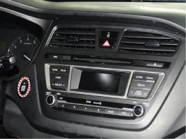
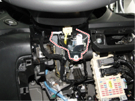
| System Status | Terminal status | ESCL status | ENGINE STATUS |
| 1. OFF - locked | OFF | LOCKED | STOP |
| 2. OFF - unlocked | OFF | unlocked | STOP |
| 3. ACC | SOUND | unlocked | STOP |
| 4. ALL | ALL1, ALL2, ACC | unlocked | STOP |
| 5. Start | IGN1, START | unlocked | Starting |
| 6. ALL - engine | ALL1, ALL2, ACC | unlocked | RUNNING (means "rotates alone") |
Regarding terminals, the system states are described in the table above. They are the same as for a system based on a mechanical ignition switch. The only difference from a mechanical ignition switch system is that the BES system allows a specific transition from [OFF] to [START] without passing through the [ACC] and [ALL] states. BES SYSTEM STATES IN PRIMARY MODE. The BES system can be set to 5 different states (OFF, LOCKED, if not available in empty mode), depending on the state of the terminals, ESCL and engine:
| System Status | Terminal status | ESCL status | ENGINE STATUS |
| 1. OFF - UNLOCKED | OFF | unlocked | STOP |
| 2. ACC | SOUND | unlocked | STOP |
| 3. ALL | ALL1, ALL2, ACC | unlocked | STOP |
| 4. Departure | IGN1, START with special activation model, see section 6.2.1. details | unlocked | Starting |
| 5. ALL - engine | ALL1, ALL2, ACC | unlocked | RUNNING (means "rotates alone") |
Regarding terminals, the system states are described in the table above. They are the same as for a system based on a mechanical ignition switch. The only difference from a mechanical ignition switch system is that the BES system allows a specific transition from [OFF] to [START] without passing through the [ACC] and [ALL] states.
Test yourself
A quick Hyundai i20 quiz: every answer comes with an explanation and a link to the manual page.
Was this page helpful?