Body Electrical System
Instrument Cluster Description and Operation
In this manual: Body Electrical System
4steps
~24min
2/5difficulty
Done 0 of 4
Description
Communication Network Diagram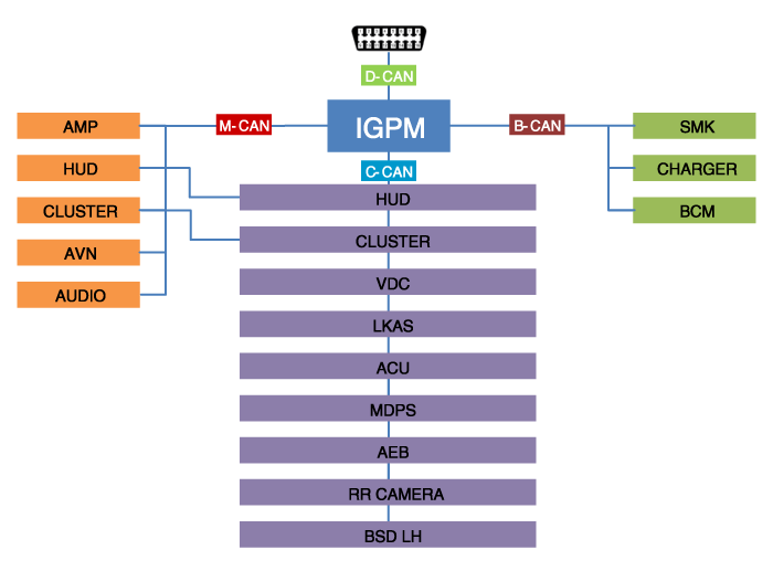
| Abbreviation | Description |
| ACU | Airbag Control Unit |
| AEB | Autonomous Emergency Braking |
| AMP | Amplifier |
| AVN | Head Unit (Audio/AVN) |
| B_CAN | Body Controller Network |
| BCM | Body Control Module |
| BCW | Blind-Spot Collision Warning Indicator |
| C_CAN | Chassis Controller Area Network |
| CLU | Cluster Module |
| CAMERA | Rearview Camera |
| M_CAN | Multimedia Controller Network |
| MDPS | Motor Driven Power Steering |
| P_CAN | Power Train Controller Area Network |
| SJB | Smart Junction Box |
| SMK | Smart Key Unit |
Cluster Option Coding. Since the vehicle has more options (ESC, MDPS, SCC, etc.), the instrument cluster now has more information to display depending on the selected options. For this reason, it is necessary to know the options of the current vehicle when replacing the instrument cluster. To solve this problem, a learning course is performed based on the required option for the vehicle when replacing the instrument cluster. This is called variant coding. Function
- High-Speed CAN Communication (C-CAN)
- Custom Function: Welcome Light (Lighting Delay Function)
- LDW: Lane Departure Warning
- SPAS: Smart Parking Assist System
- Low-Speed CAN Communication (MM-CAN)
- AV: Audio/Video Multimedia Information Display
- TBT: Turn-by-Turn Navigation Information Display
- Sound Output. The instrument cluster and external speakers are connected to output various signals and sound effects. If an external amplifier is applied, the directional alarm is output through the amplifier.
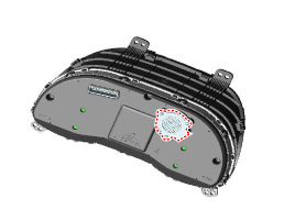
- User Setting Mode (USM)
The settings can be changed using the switches (MENU, UP, DOWN and OK button). There are many items (for example, In/Out Seat Synchronization, In/Out Steering Wheel Synchronization, Auto Door Lock, Auto Door Unlock Cancel, Headlamp Follow Me, Welcome Light, Welcome Sound, One-touch Turn Signal, Average Fuel Consumption Auto Reset, Brightness and Content Setting) that can be set and adjusted. The signal flow during setting is as follows.- USM settings are configured and transmitted to the BCM.
- The BCM transmits the settings via B-CAN to the corresponding modules.
- The module completes the setting and transmits the changed setting to the BCM.
- The BCM transmits the final settings via C-CAN to the cluster.
Test yourself
A quick Hyundai Kona quiz: every answer comes with an explanation and a link to the manual page.
Was this page helpful?