Body Electrical System
Instrument Cluster Repair Procedures
In this manual: Body Electrical System
18steps
~108min
4/5difficulty
Done 0 of 18
Removal
- Disconnect the negative (-) battery terminal.
- Remove the cluster fascia panel. (Refer to Body - Instrument Panel)
- Separate the instrument cluster (A) after loosening the mounting screws.
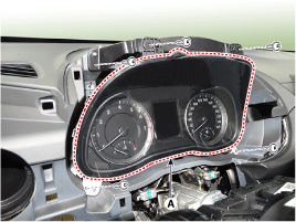
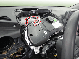
- Remove the instrument cluster after disconnecting the instrument cluster connector (A).
Installation
- Install the cluster after connecting the cluster connectors.
- Install the cluster fascia panel.
- Connect the negative (-) battery terminal.
Inspection
- Checkpoint (Warning Lamp)
No Reference Symbol Name Color Input Signal Signal Control Checkpoint 1 
Turn Signal (Left) Green CAN Gateway
(Gateway)- Multifunction switch
- BCM
- CAN Failure
2 
Turn Signal (Right) Green CAN Gateway
(Gateway)- Multifunction switch
- BCM
- CAN Failure
3 
Rear Lamp Green CAN Gateway
(Gateway)- Multifunction switch
- BCM
- CAN Failure
4 
Fog Lamp Green CAN Gateway
(Gateway)- Multifunction switch
- BCM
- CAN Failure
5 
High Beam Blue CAN Gateway
(Gateway)- Multifunction switch
- BCM
- CAN Failure
6 
Warning Yellow CAN BCW - BCW System
- CAN Failure
SCP - TPMS System
- CAN Failure
CCS - SCC System
- CAN Failure
LDW - LDW System
- CAN Failure
FCA - FCA System
- CAN Failure
HBA - HBA System
- CAN Failure
BCM - Outside Lamp
- BCM
- CAN Failure
Hard Wired Low Washer - Washer Fluid Level Sensor
- Wiring Fault
Digital Input Service Reminder Indicator 7 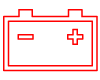
Battery Charge Red Hard Wired Generator - Generator
- Wiring Fault
- Battery
8 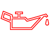
Oil Pressure Red Hard Wired ECM - Oil pressure sensor
- Wiring Fault
- ECM
- CAN Failure
9 
Check Engine Yellow CAN ECM - ECM
- CAN Failure
10 
Immobilizer Yellow MAY
+
Hard WiredIMMOBILIZER
SMK- Immobilizer System
- SMK
- BCM
- CAN Failure
- Hard Wired
11 
Parking Brake
Brake Fluid
EBD
EPB
Executive Vice PresidentRed CAN bcm
(Gateway)
EBD
EPB
Executive Vice President
ABS
TCS- BCM
- ABS System
- EPB System
- CAN Failure
- Parking Brake Switch
- Brake Fluid Level Sensor
12 
ABS Yellow CAN ABS - ABS System
- CAN Failure
13 
ESC Yellow CAN TCS - ABS System
- CAN Failure
14 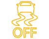
ESC OFF Yellow CAN TCS - ABS System
- CAN Failure
17 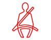
Seat belt Red CAN Gateway
(Gateway)- BCM
- CAN Failure
18 
Air Bag Red CAN SRSCM - SRSCM System
- CAN Failure
19 
EPS
(MDPS)Red CAN MDPS - MDPS Unit System
- MDPS Motor
- CAN Failure
20 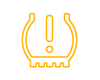
SCP Yellow CAN SCP - TPMS System
- TPMS Sensor
- CAN Failure
21 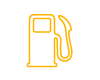
Fuel Warning Yellow Direct
(Micom)Fuel Sender - Fuel Sensor Failure
- Wiring Fault
22 
Door Open Red CAN Gateway
(Gateway)- BCM
- CAN Failure
- Door Sensor/Switch
23 
ECO Green Hard Wired ECO Mode - Drive Mode Switch
- ECU System
- TCU System
24 
SPORT Yellow Hard Wired SPORT Mode - Drive Mode Switch
- ECU System
- TCU System
25 
CRUISE Green CAN ECM - ECM
- CAN Failure
26 
SET Green CAN ECM - ECM
- CAN Failure
27 

AUTO HOLD Green
YellowCAN ECM - ECM
- CAN Failure
- TR Switch (Sensor)
No Name Input Signal Signal Control
(Unit/Sensor)Checkpoint 1 Speedometer C-CAN ABS/ESC 1) CAN line failure 3 Tachometer C-CAN Emergency Call 1) CAN line failure 4 Engine Coolant Temperature C-CAN Emergency Call 1) CAN line failure 5 Fuel Hard Wire Fuel Grinder 1) Fuel level sensor malfunction 2) Wiring malfunction 6 Shift Lever Indicator C-CAN TCU 1) CAN line failure - Body electrical system malfunctions can be quickly diagnosed with the Global Diagnostic System (GDS). The GDS provides the following information.
- Self-Diagnosis: Diagnostic Trouble Code (DTC) check and display
- Current Data: Check the system input/output status.
- Actuator Test: Checking System Operating Status
- Additional function: other control such as option system and zero point setting
- Select "Vehicle Model" and the system to be checked to inspect the vehicle with the tester.
- Select "Body Control Module (BCM)" to check the "Cluster Module (CLU)".
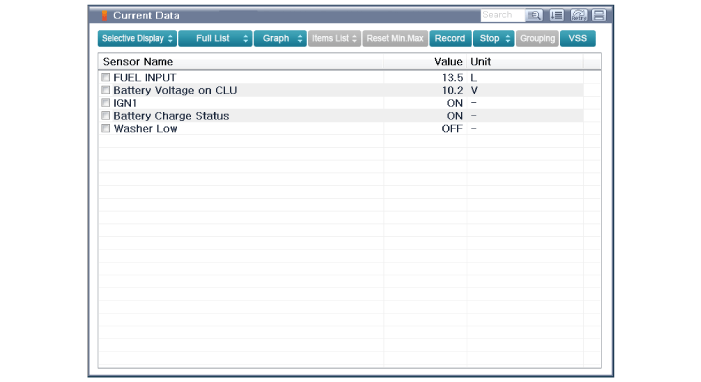
- Select the "Current Data" menu to check the current status of input/output data. Input/output data for the sensors related to the Cluster Module (CLU) can be checked.
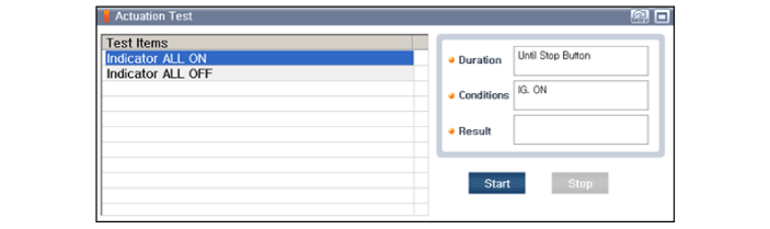
- To check the input value of the cluster illumination, select the "Active Test" option.
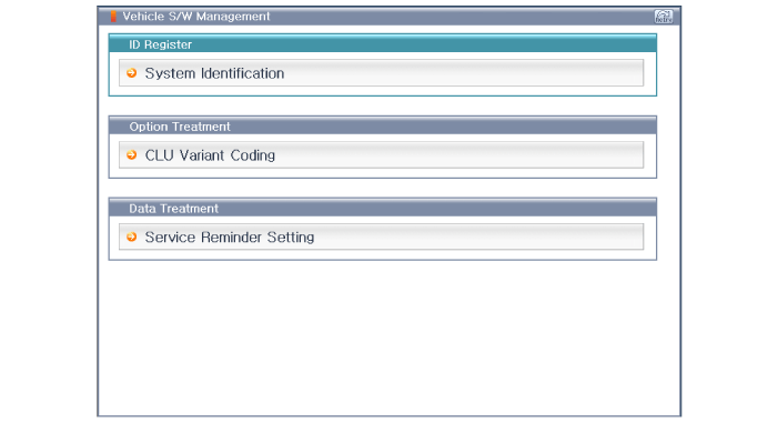
- Connect the GDS cable to the data link connector located on the driver side lower panel, then turn on the GDS power.
- Select the model and "BCM".
- Select Variant Coding mode to perform.
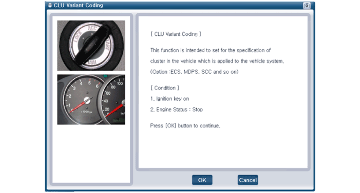
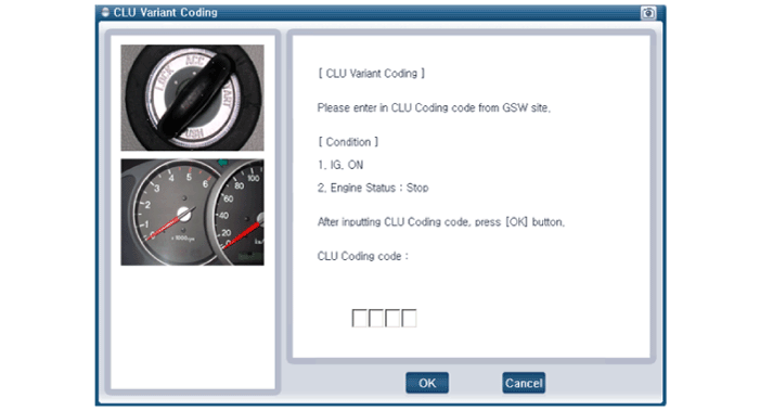
- If diagnostic trouble codes occur while performing variant coding, check the installation condition of the CLU, then try the CLU variant coding again.
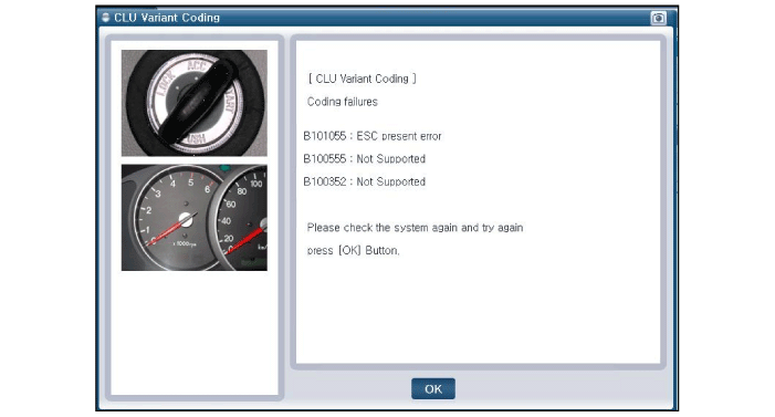
After replacing the cluster with a new one, perform "Variant Coding".
Test yourself
A quick Hyundai Kona quiz: every answer comes with an explanation and a link to the manual page.
Was this page helpful?