MFC Variant Coding
MFC variant coding allows the functions to be configured for each vehicle type. If the variant code differs from the vehicle specification, the DTC "Variant Coding Error" is displayed.
Variant Coding Procedure
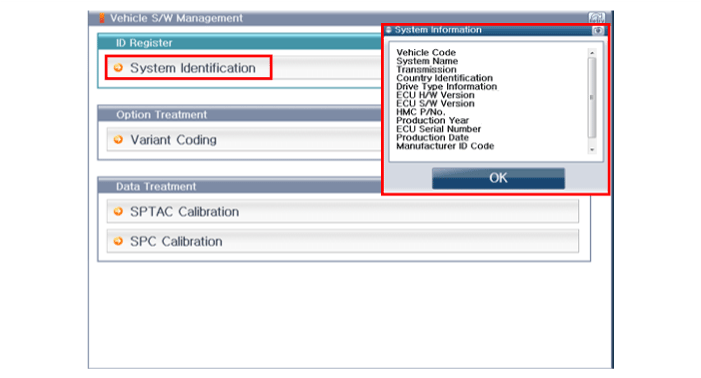
Read the specification information of the MFC installed in the vehicle before replacing it with a new MFC.
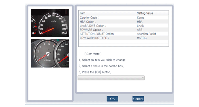
Select the specification information from the additional function.
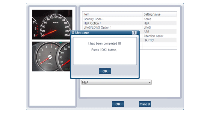
Enter the specification value read in step (2) into the new MFC.
Service Point Target Automatic Calibration (SPTAC)
When calibration is required:
MFC Removal and Installation
Replace the MFC with a new one.
Windshield Replaced
MFC Windshield Bracket Deformed
MFC Service Point Target Automatic Calibration (SPTAC)
SPTAC provides the service technician with a method to calibrate the camera by aligning the calibration target (SST: 09890-3V100) with the vehicle on level ground. If calibration is not completed within the specified tolerance, the DTC "System Out of Calibration" is displayed in the MFC.
Calibration Target Alignment Method
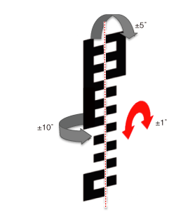
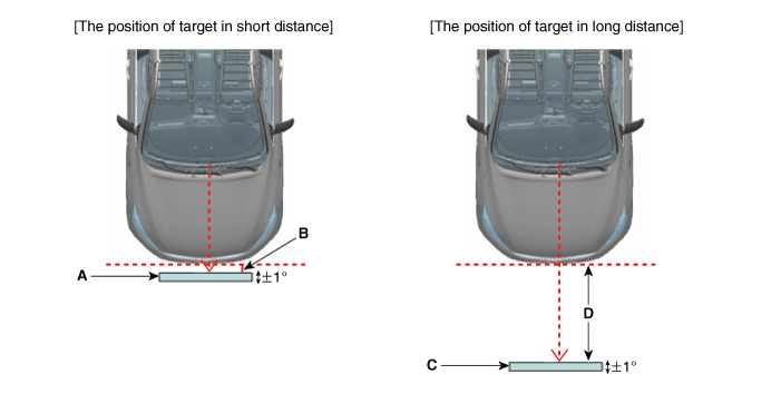
For successful MFC calibration, install the calibration target as follows:
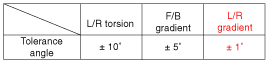
Install the target (SST: 09890-3V100) perpendicular to the ground and at the camera-related lower corner tolerance.
Service Point Target Automatic Calibration (SPTAC) Procedure
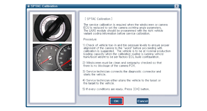
It is recommended to check the vehicle toe alignment and tire pressure levels to ensure correct camera alignment to the "world" before starting calibration. The vehicle must be at nominal production load capacity when starting the calibration procedure.
The windshield must be clean and free of silkscreen so that there is no camera obstruction.
The service technician connects the diagnostic connector and starts the vehicle. The MFC must not be activated by pressing the switch.
The service calibration procedure may not operate correctly if any system-level fault is active.
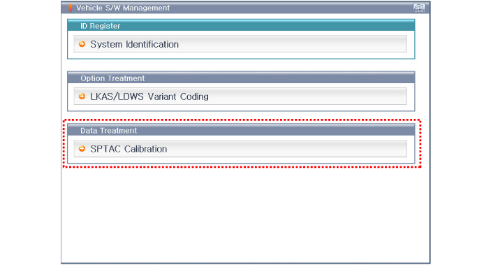
When working with a replacement ECU: the service technician initiates the SPTAC reset setting.
The service technician aligns either the vehicle to the target or the target to the vehicle.
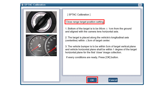
a. Position the lower edge of the target at 90 cm from the ground (max. tolerance: 1 cm).
b. Position so that the center axis of the target and the center axis of the vehicle coincide (max. tolerance: 3 cm).
c. Position the near target (A) at 0 cm (B) from the front of the bumper (max. tolerance: 5 cm).
d. Position the far target (C) at 100 cm (D) from the front of the bumper (max. tolerance: 5 cm).
Select "Camera Calibration" in the Global Diagnostic System (GDS).
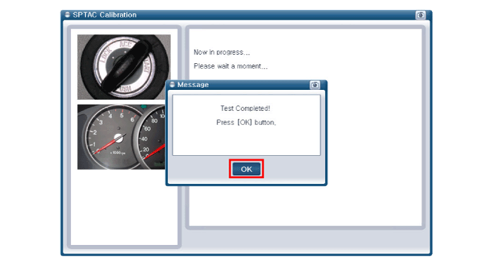
The service technician must perform short-distance calibration after checking the target location and the "OK" message on the GDS.
The service technician must perform long-distance calibration after checking the target location and the "OK" message on the GDS (perform calibration twice: short distance and long distance).
Test Drive
Intelligent High Beam (SHB)
?
Test yourself
A quick Hyundai Kona quiz: every answer comes with an explanation and a link to the manual page.