Advanced Driver Assistance System (ADAS)
Description and Operation
In this manual: Advanced Driver Assistance System (ADAS)
12steps
~72min
3/5difficulty
Done 0 of 12
Description
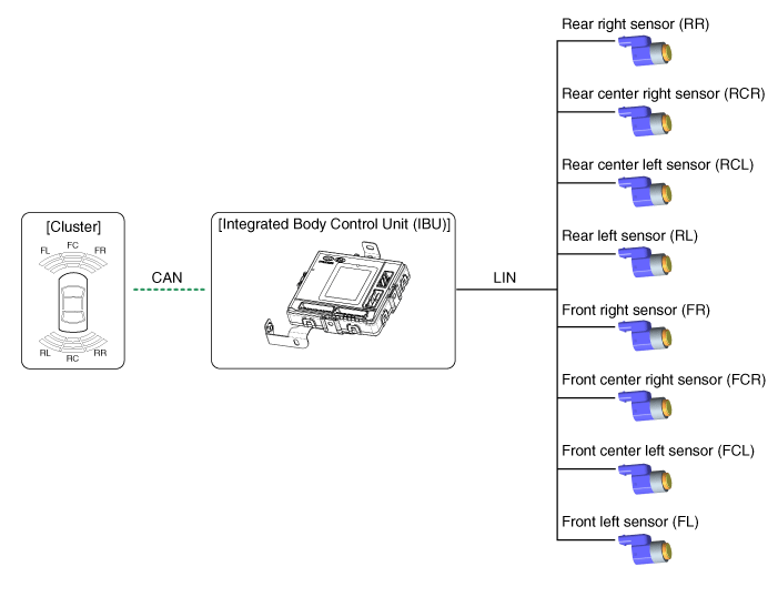
- The PDW consists of 8 sensors (front: 4 pcs., rear: 4 pcs.), which are used to detect obstacles and transmit the result as three separate warning levels: first, second and third, to the IBU via LIN communication.
- The IBU determines the warning level from the communication message transmitted by the slave sensors, then activates the buzzer or transmits data for display.
Initial Mode
- System Initialization Time
- PDW-F: 500 ms after IGN1 ON + initial D transmission + below 10 km/h
- PDW-R: 500 ms after IGN1 ON + initial R gear
- The PDW recognizes the LID and sets the sensor ID during initialization.
- The PDW activates each sensor and then performs diagnostics after IPM (IBU) initialization is completed.
- The PDW start buzzer operates normally when no sensor sends an error message and after error diagnostics are completed.
- If any failure is received from any sensor, the PDW start buzzer does not operate, but the warning buzzer sounds briefly. If equipped with a display, the warning symbol is also shown on it.
The buzzer sounds once when a sensor fails, but the display is shown continuously until the system is fully repaired.
- The IBU stores the completed sensor initialization status.
Normal Mode
- PDW-F: Line communication starts and maintains the procedure after IGN1 ON + D transmission + below 10 km/h. PDW-R: Line communication starts and maintains the procedure after IGN1 ON + R gear
- After initialization, the subroutine runs immediately without the PDW warning sound.
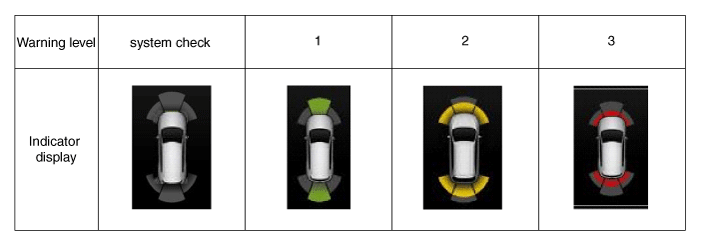
- The obstacle warning consists of 3 levels: 1, 2, 3 steps, and levels 1 and 2 sound intermittently, level 3 sounds continuously. Level 1 warning is not present in the front ultrasonic sensor.
- On the display, the data of each sensor is sent from the IBU to the instrument cluster display. CAN communication is used for transmission, and the maximum gateway time is 50 ms.
- The effective vehicle speed for PDW operation is less than 10 km/h.
- Operation does not start or stops in N or P gear.
| Level | Distance Range | Allowable Range |
| 1 | Front: 61–100 cm (24.02–39.37 in.) / Rear: 61–120 cm (24.02–47.2 in.) | ± 15 cm (5.90 in.) |
| 2 | 31–60 cm (12.20–23.62 in.) | ± 15 cm (5.90 in.) |
| 3 | 0–30 cm (0–11.81 in.) | ± 10 cm (3.94 in.) |
*Measurement conditions: PVC pipe - diameter 75 mm (0.0394 in.), length 1 m (39.37 in.), at normal temperature. Warning indicator display specification
Test yourself
A quick Hyundai Palisade quiz: every answer comes with an explanation and a link to the manual page.
Was this page helpful?