1. Fuel pump adapter 2. Camshaft bearing cap 3. Front camshaft bearing cap 4. Exhaust camshaft
5. Intake camshaft 6. Exhaust CVVT 7. Intake CVVT
Description and Operation
Description
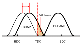
The Continuously Variable Valve Timing (CVVT) system advances or retards the valve timing of the intake and exhaust valves according to the control signal from the ECM, calculated based on engine load and speed. CVVT control reduces valve overlap or underlap, resulting in better fuel economy, reduced exhaust emissions (NOx, HC), improved engine performance by reducing pumping loss, improved internal exhaust gas recirculation, improved combustion stability, increased volumetric efficiency and increased torque. This system includes
CVVT oil control valve (OCV) that supplies engine oil to the cam phaser or drains engine oil from the cam phaser according to the PWM (Pulse Width Modulation) signal from the ECM,
CVVT oil temperature sensor (OTS) that measures the engine oil temperature,
and a cam phaser that changes the cam phase by hydraulic force of engine oil.
Engine oil flowing from the CVVT oil control valve changes the camshaft phaser position in the direction of engine rotation (intake advance/exhaust retard) or in the opposite direction (intake retard/exhaust advance) by rotating the rotor connected to the camshaft in the phaser.
Principle of Operation
CVVT has a mechanism that rotates the rotor valve using hydraulic force generated by engine oil supplied to the advance or retard chamber according to the CVVT oil control valve control.
[CVVT System Mode]
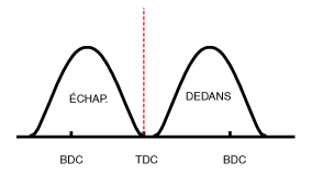
(1) Low Speed/Low Load
(2) Partial Load
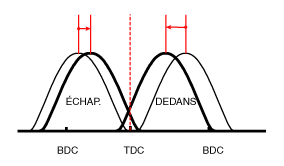
(3) Low Speed/High Load
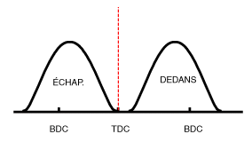
(4) High Speed / High Load
Operating Condition
Exhaust Valve
Intake Valve
Valve Timing
Effect
Valve Timing
Effect
(1) Low Speed / Low Load
Fully ADVANCE
* Valve overlap * Improved combustion stability
Fully RETARD
* Valve overlap * Improved combustion stability
(2) Partial Load
RETARD
* Improved relaxation work * Reduced pumping loss at load changes * Reduced HC
RETARD
* Reduced pumping loss at load changes
(3) Low Speed / High Load
RETARD
* Improved relaxation work
ADVANCE
* Prevention of reverse intake flow (improved volumetric efficiency)
(4) High speed / high load
ADVANCE
* Reduced pumping loss at load changes
RETARD
* Improved volumetric efficiency
Repair Procedures
DEPOSIT
It is not necessary to remove the timing chain cover during this procedure.
Remove the cylinder head cover. (Refer to Cylinder Head - "Cylinder Head Cover")
Remove the fuel pump adapter (A).
Set the No. 1 cylinder to TDC (top dead center) on the compression stroke.
Turn the crankshaft pulley and align its groove with the mark on the timing chain cover.
Make sure the TDC marks on the intake and exhaust CVVT sprockets are in a straight line on the cylinder head surface as shown in the illustration. Otherwise, turn the crankshaft one additional revolution (360°).
Mark the timing chain sprockets to match the markings on the CVVT.
Remove the crankshaft damper pulley. (Refer to Timing System - "Crankshaft Damper Pulley")
Remove the service plug bolt (A) and gasket (B).
Remove the tensioner lever bolt (A).
Lower the tensioner lever (A).
Remove the camshaft bearing caps.
First remove the exhaust camshaft (A), then remove the intake camshaft (B).
Remove the tensioner lever (A).
Remove the CVVT (A) from the camshaft.
Inspection
Camshaft
Inspect the camshaft lobes. Using a micrometer, measure the lobe height. If the camshaft lobe height is less than specification, replace the camshaft.
CAMSHAFT LOBE HEIGHT Intake: 39.0 mm (1.5354 in) Exhaust: 39.0 mm (1.5354 in)
Make sure the camshaft journal surface is not damaged. If the journal is excessively worn, replace the camshaft.
Inspect the camshaft journal oil clearance.
Clean the bearing caps and the camshaft journals.
Install the camshafts on the cylinder head.
Place a strip of Plastigage across each camshaft journal.
Install the bearing caps and tighten the bolts to the specified torque. Tightening torque: M6 bolts: 11.8 ~ 13.7 N·m M8 bolts: 18.6 ~ 23 N·m
Remove the bearing caps.
Measure the plastigage at the widest point. If the oil clearance exceeds the specification, replace the camshaft. If necessary, replace the bearing caps and the cylinder head assembly.
Using a dial indicator, measure the camshaft end play by moving the camshaft back and forth. If the end play exceeds the specification, replace the camshaft. If necessary, replace the bearing caps and the cylinder head assembly. Camshaft end play STANDARD: 0.10 ~ 0.19 mm (0.0039 ~ 0.0075 in)
Remove the camshafts.
Check that the CVVT rotates smoothly.
Secure the camshaft in a vise. Be careful not to damage the camshaft lobes and journals.
Make sure the CVVT is locked by attempting to rotate it clockwise and counterclockwise. It must not rotate.
Intake CVVT: Seal one of the two holes in the camshaft journal with tape. Exhaust CVVT: Seal one of the two retard holes in the camshaft journal with tape.
Intake CVVT: Apply approximately 150 kPa (1.5 kgf/cm², 21 psi) of compressed air to the unsealed advance hole to unlock the CVVT. Exhaust CVVT: Apply approximately 150 kPa (1.5 kgf/cm², 21 psi) of compressed air to the unsealed retard hole to unlock the CVVT.
Intake CVVT: While applying compressed air, rotate the CVVT in the advance direction (counterclockwise) within the phase range and make sure the CVVT rotates smoothly. Exhaust CVVT: While applying compressed air, rotate the CVVT in the retard direction (clockwise) and make sure the CVVT rotates smoothly. CVVT phase range Intake: 25° ± 0°30' (from maximum retard position to maximum advance position) Exhaust: 20° ± 0°30' (from maximum advance position to maximum retard position)
Intake CVVT: Rotate the CVVT to the maximum retard position (clockwise), then make sure the CVVT is locked. Exhaust CVVT: Rotate the CVVT to the maximum advance position (counterclockwise), then make sure the CVVT is locked.
Compress the tensioner piston using the handle (A), then insert the stopper pin (B) into the hole in the tensioner to hold the compressed piston.
Install the intake camshaft (A), then engage the tensioner lever (B) with the timing chain.
Install the exhaust camshaft (A).
Install the camshaft bearing cap.Tighten the bolts in several passes in the sequence shown. Tightening torque: M6 bolts: 11.8 ~ 13.7 N·m M8 bolts: 18.6 ~ 23 N·m
Using a suitable tool, move the tensioner lever to align the tensioner bolt hole with the service hole.
Install the tensioner lever bolt (A).
Tightening Torque: 18.6 ~ 23 N·m
Remove the tensioner stopper pin.
Turn the crankshaft two revolutions in the direction of engine rotation (clockwise), then check that the TDC marks on the CVVT sprockets are aligned in a straight line with the cylinder head surface.
Install the service plug bolt (A) with a new gasket.
Tightening torque: 29.4 – 39 N·m
Install the crankshaft damper pulley. (Refer to Timing System - Crankshaft Damper Pulley)
Install the cylinder head cover. (Refer to Cylinder Head - "Cylinder Head Cover")
?
Test yourself
A quick Hyundai Tucson quiz: every answer comes with an explanation and a link to the manual page.