AUTOMATIC TRANSMISSION SYSTEM
Automatic Transmission
In this manual: AUTOMATIC TRANSMISSION SYSTEM
29steps
~199min
5/5difficulty
5special tools
Done 0 of 29
Components and Component Location
Component Location (1)

| 1. Automatic Transmission Assembly 2. ATF Cooler Tube 3. Ground Line 4. Shift Cable Bracket 5. Shift Cable 6. Lock Switch and Manual Lever |
7. Clamp 8. ATF Cooler Hose 9. Radiator and ATF Cooler 10. Mounting Bracket Cover 11. Bracket Mounting Bolt 12. Automatic Locking Bracket |
Component Location (2)

| 1. Automatic Transmission Assembly 2. Subframe |
3. Tie Rod Support Bracket 4. Roller Support |
Repair Procedures
DEPOSIT
- Remove the engine cover. (Refer to Engine Mechanical System - "Engine Cover")
- Remove the air duct and air cleaner assembly. (Refer to Engine Mechanical System - "Air Cleaner")
- Disconnect the battery and battery tray. (Refer to Engine Electrical System - "Battery".)
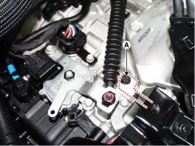
- Remove the ground line after removing the bolts (A).
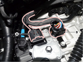
- Disconnect the solenoid valve connector (B) and the inhibitor switch connector (A).
- Remove the control cable (B) by unscrewing the nut (C) and bolt (A). Tightening torque: (A) 14.7 ~ 22 N·m (C) 9.8 ~ 14.7 N·m
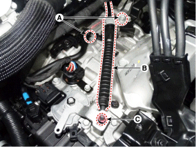
- Remove the fixing clips (A) from the wiring harness (B).
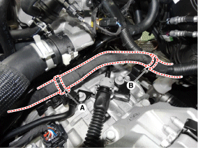
- Remove the retaining bracket (A) from the wiring harness.
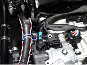
- Remove the ATF cooler tubes (A).
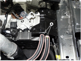
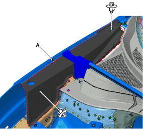
- Remove the fender apron cover (A) from both sides.
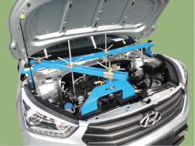
- Install the engine support bracket (Frame No.: 09200-38001 or 09200-3N000, Service Support No.: 09200-2S000). (Refer to Special Service Tools - "Engine Support Bracket Installation Diagram")
- Using the engine support bracket (A), carefully support the engine and the entire transmission.
- Remove the upper bolts of the automatic transmission mounting (A, 2 pcs.) and starter (B, 2 pcs.). Tightening torque: (A) 42.2 ~ 54 N·m (B) 42.2 ~ 54 N·m
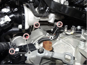
- Remove the fender. (Refer to Body - "Body Side Moulding")
- Remove the bracket cover from the automatic transmission mounting bracket bolts (A).
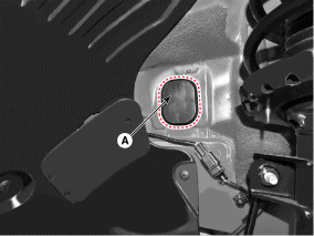
- Remove the automatic transmission bracket mounting bolt (B).
Tightening torque: 88.3 ~ 108 N·m
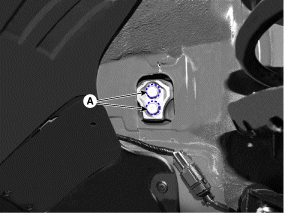
- Remove the support (A) from the automatic transmission.
Tightening torque: 58.8 ~ 78 N·m
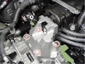
- Raise the vehicle using a jack.
- Remove the under cover. (Refer to Mechanical System - "Engine Room Under Cover")
- Disconnect the assembly from the drive shaft. (Refer to Axle and Drive Shaft - "Front Drive Shaft")
- Remove the stabilizer bar (C) by loosening bolts (A) and (B). Tightening torque: Bolt (B): 107.9 ~ 128 N·m Bolt (A): 49.0 ~ 64 N·m
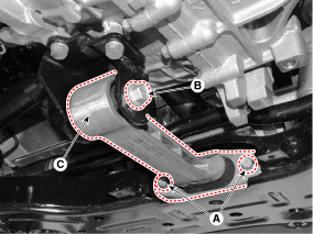
- Remove the idler arm bracket (A).
Tightening torque: 49.0 ~ 69 N·m
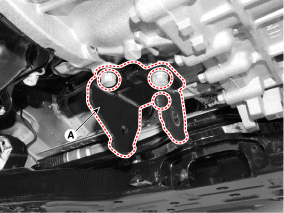
- Remove the stabilizer bar (C) after removing bolts (A) and (B). Tightening torque: (A) 11.8 ~ 13.7 N·m (B) 21.6 ~ 26 N·m
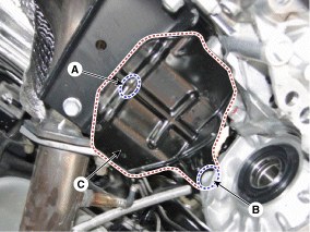
- Remove the dust cover (A).
Tightening torque: 42.2 ~ 48 N·m
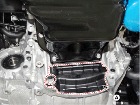
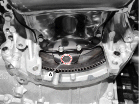
- Remove the torque converter mounting bolts (A) by turning the crankshaft.
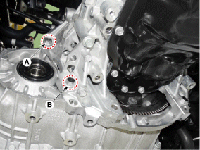
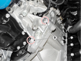
- Remove the A/T with a jack after removing the mounting bolts (A, B). Tightening torque: (A) 42.2 ~ 54 N·m (B) 42.2 ~ 48 N·m
REMEDY
- To install, perform the removal procedure in reverse order.
- In case of relocation.
- Replace the seal with a new one if ATF leaks. This is caused by damage to the oil seal.
- Check the ATF level after filling the A/T with fluid. (Refer to Hydraulic System - "Fluid")
- Clear the diagnostic trouble codes (DTC) using GDS.
- When replacing with a new A/T.
- Place an air gun in front of the ATF cooler hose (A).
- Remove the remaining ATF by blowing air through the hose. ATF cooler (A).
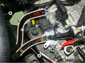
- Connect the ATF cooler hoses (A) and (B).
- Clear the diagnostic trouble codes (DTC) using GDS.
- Reset the automatic transmission adaptive values using GDS.

- Perform the TCM adaptive value learning procedure. (Refer to Automatic Transmission Control System - "Repair Procedures")
Test yourself
A quick Hyundai Tucson quiz: every answer comes with an explanation and a link to the manual page.
Was this page helpful?