Body Electrical System
Instrument Cluster
In this manual: Body Electrical System
28steps
~168min
5/5difficulty
Done 0 of 28
Components and Component Location
COMPONENTS
[Standard Type (3.5 inch)]


| No. | Description | No. | Description |
| 1 | MASS | 21 | Day switch (-) |
| 2 | ILLUMINATION (-) | 22 | Day switch 1 (+) |
| 3 | Input (low) rheostat switch | 23 | Day switch 2 (+) |
| 4 | Input (high) rheostat switch | 24 | - |
| 5 | Relaxation | 25 | Speaker (-) (monitor type only) |
| 6 | A/T ("P" position) | 26 | Speaker (-) (monitor type only) |
| 7 | A/T ("R" position) | 27 | - |
| 8 | AT ("N" Position) | 28 | - |
| 9 | A/T ("D" position) | 29 | Multimedia CAN (Low) |
| 10 | AT ("S" Position) | 30 | Multimedia CAN Bus (High) |
| 11 | - | 31 | Driver Mode Switch_Input (AT only) |
| 12 | Oil pressure switch input (gasoline only) | 32 | Chassis CAN (HIGH) |
| 13 | Alternator_Input (gasoline only) | 33 | CAN (BAS) Chassis |
| 14 | Fuel sender input (-) | 34 | Washer Low Level Signal |
| 15 | Airbag (+) input | 35 | Water separator (diesel only) |
| 16 | Fuel sender input (-) | 36 | MASS |
| 17 | Immobilizer input | 37 | MASS |
| 18 | Vehicle speed output | 38 | Flex steering wheel (TM only) |
| 19 | - | 39 | ALL 1 |
| 20 | Rear lamp input | 40 | Battery (+) |
Circuit Diagrams
Wiring Diagram
[General Standard]


[General Warning]


Description and Operation
Description
Communication Network Diagram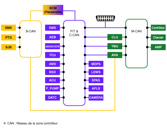
| ABBREVIATIONS | Description |
| ACU | Airbag Control Unit |
| ABS | Anti-Lock Braking System (ABS) |
| AEB | Autonomous Emergency Braking |
| AFLS | Adaptive Front Lighting System |
| Amperes | Booster |
| AVN | Headlamp Unit (Audio/AVN) |
| B_CAN | Body Controller Network |
| BCM | Body Control Module |
| BSD | Blind-Spot Detection System |
| C_CAN | Chassis Controller Area Network |
| EMB | Instrument Cluster Module |
| CAMERA | Rearview Camera |
| DATC | Temporary Command. Dual Automatic |
| ESC | Electronic Stability Program |
| EPB | Electronic Parking Brake (EPB) |
| Emergency Call | Engine Control System |
| FUEL PUMP | Fuel pump |
| LDWS | Lane Departure Warning System |
| M_CAN | Media Controller Zone Network |
| DBDM | Motor Driven Power Steering |
| P_CAN | Power Train Controller Area Network |
| PTG | POWER LIFTGATE |
| SJB | Smart Junction Block |
| SMK | Smart Key |
| SPAS | Intelligent Parking Assist System |
| UCT | Transmission Control Unit |
| TMU | Telematics System |
| 4WD | All-Wheel Drive System |
Variant Coding of the Instrument Cluster: Since the vehicle now has more options (ESC, MDPS, etc.), the instrument cluster displays additional information depending on the selected options. Therefore, it is necessary to know which options the vehicle has when replacing the instrument cluster. To solve this, the options for the specific vehicle must be checked when replacing the cluster. This is called "variant coding". Function
- High-Speed CAN Communication (C-CAN)
- User function: Automatic seat with lever on/off motion, welcome light
- LDWS: Lane Departure Warning System
- SPAS: Smart Parking Assist System
- Low-speed CAN communication (M-CAN)
- AV: Multimedia Audio/Video Information Display
- TBT: Turn-By-Turn navigation information display
- Audio output: Various warning chimes and sound effects are played through the external speakers connected to the instrument panel. If an external amplifier is applied, the directional warning is output through the amplifier.

Her Description and Function (CAN Data Receiver) Welcome Welcome (Smart key removed state and door open/closed status confirmed by BCM) Goodbye Goodbye (group) Door open warning Key reminder warning (BCM): vehicle speed is equal to or less than 5 km/h and the ALL switch is in ACC or ALL position, or the engine is started, and when the vehicle speed is below 5 km/h or when the driver's door is open Seat belt warning Driver Unfastened Seat Belt Warning (BCM) PAS system buzzer PAS sensor error warning (BCM) R speed PAS warning when shifting to R (BCM and SPAS) PARKING BRAKE Parking Brake Warning (BCM) START button SSB (SMK) warning button Rheostat LED information Rheostat warning when maximum or minimum level is selected (group) Smart key exit Smart Exit key warning (SMK) Smart Exit key No warning (SMK) Conditional speed Change normal gear Turn signal lamp Turn signal warning (BCM) Turn indicator (Current) Turn signal warning (BCM) Smart key battery low voltage Warning when the driver presses the SSB button with a low-voltage smart key battery (SMK) EPB buzzer Buzzer when switching from automatic to locking EPB (EPB) Coolant Temperature Warning When engine temperature is above 120ºC (EMS) - User Setting Mode (USM): The setting can be changed using the switches (MENU, UP, DOWN and OK button). Several items (for example, seat entry/exit synchronization, steering wheel entry/exit synchronization, automatic door locking, automatic door lock cancellation, headlight follow-me function, welcome light, welcome sound, one-touch flashing light, automatic reset of fuel consumption average, brightness and content configuration) can be set and adjusted. Traffic light signals during setting are as follows.
- USM settings are determined and transmitted to the BCM.
- The BCM transmits the settings via B-CAN to the corresponding modules.
- The module completes the setting and transmits the changed setting to the BCM.
- The BCM transmits the final settings to the instrument cluster via C-CAN.
Repair Procedures
DEPOSIT
Instrument Cluster- Disconnect the negative (-) battery terminal.
- Remove the instrument cluster panel. (Refer to Body — Lower Instrument Panel)
- Separate the instrument cluster (A) by loosening the mounting screws.

- Remove the instrument cluster after disconnecting the instrument cluster connector (A).

- Disconnect the negative (-) battery terminal.
- Remove the instrument cluster upper panel. (Refer to Body - Lower Instrument Panel)
- Separate the speaker from the instrument cluster (A) by loosening the screw.

- Remove the speaker from the instrument cluster (A) after disconnecting the speaker connector (B).

REMEDY
Instrument Cluster- Install the speaker after connecting the instrument cluster connectors.
- Install the instrument cluster panel.
- Connect the negative (-) battery terminal.
- Install the instrument cluster speaker after connecting the instrument cluster connectors.
- Install the instrument cluster upper panel.
- Connect the negative (-) battery terminal.
Inspection
- Checkpoint (indicator lamp)
NO Symbol No. Name Color Input Signal Signal command Checkpoint 1 
Flashing light (left) GREEN CAN BGM
(Bridge)- With multifunction switch
- BCM
- CAN malfunction
2 
Flashing light (right) GREEN CAN BGM
(Bridge)- With multifunction switch
- BCM
- CAN malfunction
3 
Tail Light GREEN CAN BGM
(Bridge)- With multifunction switch
- BCM
- CAN malfunction
4 
FOG
Fog lampsGREEN CAN BGM
(Bridge)- With multifunction switch
- BCM
- CAN malfunction
5 
Rear Fog Lamp YELLOW CAN BGM
(Bridge)- With multifunction switch
- BCM
- CAN malfunction
6 
Headlamps GREEN CAN BGM
(Bridge)- With multifunction switch
- BCM
- CAN malfunction
7 
LED
HeadlampYELLOW CAN BGM
(Bridge)- BCM
- CAN malfunction
8 
Red lights BLUE CAN BGM
(Bridge)- With multifunction switch
- BCM
- CAN malfunction
9 
Main symbol YELLOW CAN BSD - BSD System
- CAN malfunction
SCP - TPMS system
- CAN malfunction
BCM - Exterior Lighting
- BCM
- CAN malfunction
Cable Fuel sensor - Fuel Sender Malfunction
- Wiring Fault
LOWER WASHER - Windshield washer fluid level sensor
- Wiring Fault
DIGITAL INPUT Maintenance reminders 10 
Battery Charge RED CAN ECM - Charging System
- CAN malfunction
11 
OIL PRESSURE RED Cable ECM - ECM system
- Cable
- CAN malfunction
12 
Check engine light YELLOW CAN ECM - ECM system
- CAN malfunction
13 
Immobilizer YELLOW CAN BGM
(Bridge)- SMK system
- BCM
- CAN malfunction
- Cable
14 
PARKING BRAKE
Brake fluid
EBD
EPBRED CAN BGM
(Bridge)
EBD
EPB
ABS
TCS- BCM
- ABS system
- EPB system
- CAN malfunction
- Parking Brake Switch
- Brake fluid level sensor
15 
ABS YELLOW CAN ABS - ABS system
- CAN malfunction
16 
ESC YELLOW CAN TCS - ABS system
- CAN malfunction
17 
OFF YELLOW CAN TCS - ABS system
- CAN malfunction
18 
EPB YELLOW CAN EPB - EPB system
- CAN malfunction
19 
Auto Hold WHITE
YELLOW
GREENCAN TCS - ABS system
- CAN malfunction
20 
Seat belt RED CAN BGM
(Bridge)- BCM
- CAN malfunction
21 
AIRBAG RED CAN srscm - SRSCM system
- CAN malfunction
22 
EPS
[MDPS]RED CAN DBDM - MSPP unit system
- PSDS engine
- CAN malfunction
23 
SCP YELLOW CAN SCP - TPMS system
- TPMS SENSOR
- CAN malfunction
24 
Low Fuel Warning YELLOW Direct
(Micom)fuel segment - Fuel Sender Malfunction
- Wiring Fault
25 
ECO GREEN Cable ECO Mode - ECM system
- CAN malfunction
26 
Sport YELLOW Cable sport mode - ECM system
- CAN malfunction
27 
SPEED CONTROL GREEN CAN ECM - ECM system
- CAN malfunction
28 
kit GREEN CAN ECM - ECM system
- CAN malfunction
29 
4WD YELLOW CAN AWD ECU - All-Wheel Drive System
- CAN malfunction
30 
4WD LOCK YELLOW CAN AWD ECU - All-Wheel Drive System
- CAN malfunction
31 
Diesel Particulate Filter (DPF) YELLOW CAN ECM - DPF system
- CAN malfunction
32 
ENGINE OIL LEVEL YELLOW CAN ECM - ECM
- CAN malfunction
33 
HEATER YELLOW CAN ECM - ECM
- CAN malfunction
34 
WATER SEPARATOR RED Cable Water-in-Fuel Sensor - Water-in-Fuel Sensor
- Wiring Fault
35 
Downhill Brake Control (DBC) System GREEN
YELLOWCAN TCS - BCW System
- CAN malfunction
36 
Overspeed YELLOW CAN ECM - ECM
- CAN malfunction
- Check Point (Sensor)
NO Name Input Signal Signal Command
(Unit/Sensor)Checkpoint 1 Speedometer C_CAN ABS/ESC 1) ABS System
2. CAN Line Malfunction2 Tachometer C_CAN ECM 1. ECU
2. CAN Line Malfunction3 Engine Coolant Temperature C_CAN ECM 1. ECU
2. CAN Line Malfunction4 FUEL hard wire Fuel 1) Fuel Sensor Malfunction
2. Wiring Malfunction - In the body electrical system, a fault can be quickly diagnosed using the Global Diagnostic System (GDS). The GDS provides the following information.
- Self-diagnosis: checks for malfunctions and the number of codes (DTC)
- Current data: checking the input/output status of the system
- Operation check: checks the operating conditions of the system
- Additional function: controls other functions, including additional system setup and zero point adjustment
- Select "Vehicle Model" and "Cluster Module (CLU)" to check the vehicle with the tester.
- Select the "Current Data" menu to check the current status of inputs and outputs.

- To control the input force of the module to be controlled, select the "Operation Check" option.
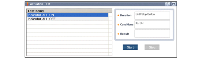
- Connect the GDS cable to the data link connector in the lower driver-side crash pad cover, GDS plug.
- Select the model and "BCM".
- Select the variant coding mode to be performed.


- If DTCs occur during variant coding, try again after checking the CLU installation status.
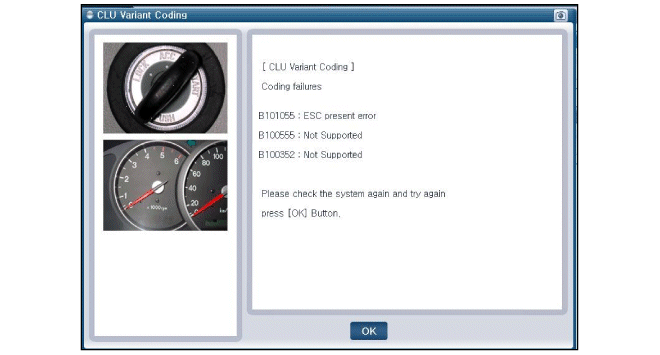
Test yourself
A quick Hyundai Tucson quiz: every answer comes with an explanation and a link to the manual page.
Was this page helpful?