Braking System
ABS Control Module
In this manual: Braking System
16steps
~96min
4/5difficulty
Done 0 of 16
Components and Component Location
Components and Component Locations
(LHD)
| 1. Front left tube 2. Rear right tube 3. Rear left tube 4. Front right tube |
5. MC2 6. MC1 7. ABS Control Module (HECU) 8. Bracket |
(DIRECT DRIVE)

| 1. Front right hose (FrontR) 2. Rear left tube (ArG) 3. Rear right tube (ArD) 4. Front left hose (Front L) |
5. MC2 (SPK) 6. MC1 (PRI) 7. ABS Control Module (HECU) 8. Bracket |
Repair Procedures
DEPOSIT
(LHD)- Turn the ignition switch to the OFF position.
- Drain the brake fluid from the master cylinder reservoir using a syringe.
- Pull up the HECU connector lock (A), then disconnect the connector.

- Loosen the nut (B) and HECU bracket bolts (B), then remove the HECU and bracket. Tightening torque: HECU bracket bolts: 16.7~26 N·m HECU bracket nut: 24.5~29 N·m

- Disconnect the brake lines from the HECU by loosening the nuts counterclockwise using a flare nut wrench.
Tightening torque: 12.7 - 16.7 N·m

Tightening Torque: 18.6 ~ 23 N·m
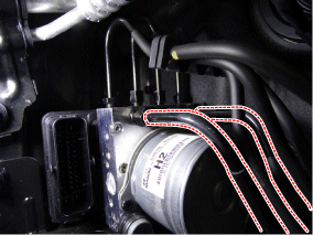
- Unscrew the bolts, then remove the HECU bracket.
Tightening torque: 10.8 ~ 13.7 N·m

- Turn the ignition switch to the OFF position.
- Drain the brake fluid from the master cylinder reservoir using a syringe.
- Pull up the HECU connector lock (A), then disconnect the connector.
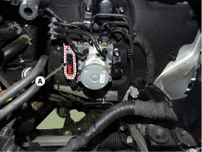
- Disconnect the brake lines from the HECU by loosening the nuts counterclockwise using a flare nut wrench. Tightening torque: A: 12.7 ~ 16.7 N·m B: 18.6 ~ 23 N·m

- Loosen the HECU bracket bolts (A), then remove the HECU and bracket.
Tightening torque: 24.5 ~ 29 N·m
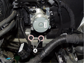
- Unscrew the bolts, then remove the HECU bracket.
REMEDY
- To install, perform the removal procedure in reverse order.
- Tighten the HECU mounting bolts and nuts to the specified torque.
- After installation, bleed the brake system. (Refer to Brake System - "Brake System Bleeding")
- Perform variant coding.
Diagnostic Procedure with Diagnostic Tool
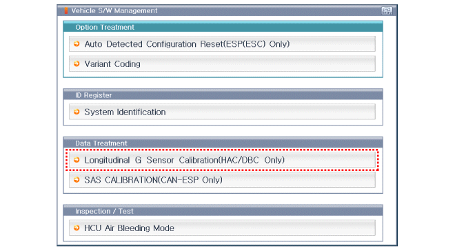
The main content of the diagnostic procedure using the diagnostic tool is as follows: Connect the self-diagnosis connector (16-pin) located in the lower part of the instrument panel to the self-diagnosis device, then turn the ignition ON to activate the device. On the vehicle selection screen, select "Vehicle Model" and "ABS/ESC" on the GDS vehicle selection screen, then click OK.[CODING OPTION]

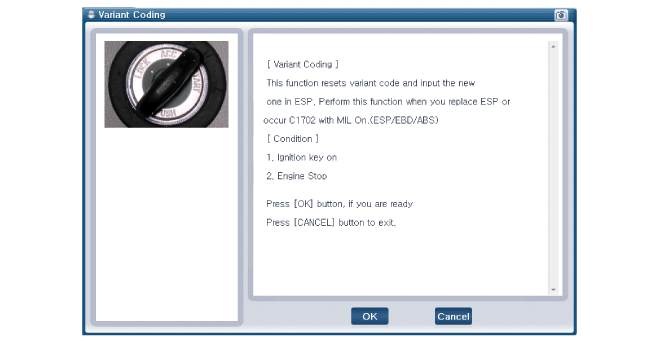
[Automatic sensor calibration detected]


[Longitudinal G-Sensor Calibration]

Test yourself
A quick Hyundai Tucson quiz: every answer comes with an explanation and a link to the manual page.
Was this page helpful?