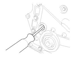
Removal of the timing chain cover is not required for this procedure.
Use fender covers to avoid damaging painted surfaces.
To avoid damage, carefully disconnect the wiring connectors by holding the connector body.
Label all wires and hoses to avoid incorrect connection.
Turn the crankshaft pulley so that the No. 1 piston is at top dead center.
Remove the cylinder head cover. (Refer to Timing System in this group)
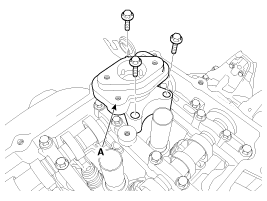
Remove the fuel pump adapter assembly (A).
Set the No. 1 cylinder to TDC (top dead center) on the compression stroke.
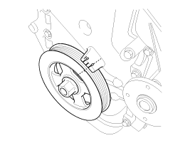
Turn the crankshaft pulley and align its groove with the alignment mark on the timing chain cover.
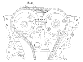
Make sure the TDC marks on the intake and exhaust CVVT sprockets are in a straight line on the cylinder head surface, as shown in the illustration. Otherwise, rotate the crankshaft one full turn (360°) or more.
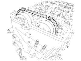
Mark the timing chains to match the alignment marks on the CVVT sprockets.
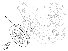
Remove the crankshaft damper pulley.
Do not press on the pulley or apply excessive force to prevent deformation of the rubber part.
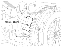
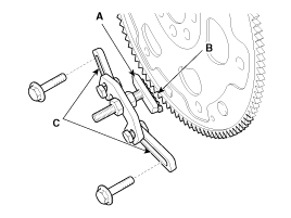
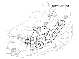
There are two methods for holding the ring gear when removing the crankshaft damper pulley.
Install SST (09231-2B100) to hold the ring gear after removing the starter.
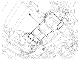
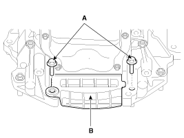
Install SST (09231-3D100) to hold the ring gear after removing the service cover.
Remove the air guard (A).
Remove the two transaxle mounting bolts (A) and remove the service cover (B) at the bottom of the oil pan.
Adjust the length of the holder (A) so that the holder grooves engage the ring gear teeth (B) in the closest position.
Adjust the angle and length of the links (C) so that the two transaxle mounting bolts can be secured in the original installation holes.
Install the SST using the two transaxle mounting bolts. Tighten the holder and link bolts and nuts securely.
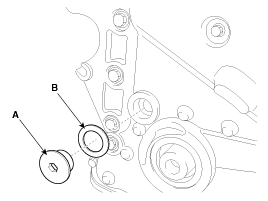
Remove the service plug bolt (A) and gasket (B).
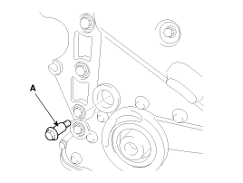
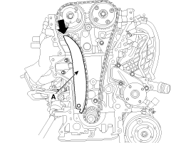
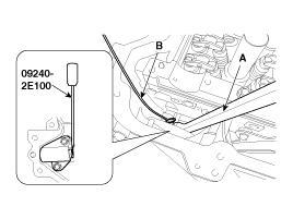
Remove the tensioner lever bolt (A).
Press the tensioner lever (A).
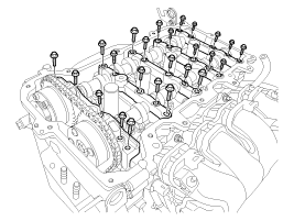
Remove the camshaft bearing caps.
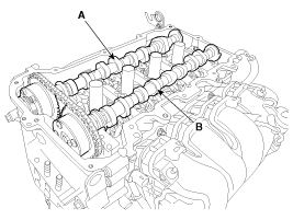
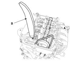
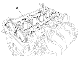
First remove the exhaust camshaft (A), then the intake camshaft (B).
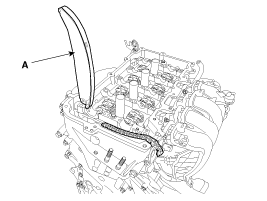
Remove the tensioner lever (A).
To hold the timing chain, secure it with a cable tie.
Installation
Compress the tensioner piston using the handle (A), then insert the stopper pin (B) into the hole in the tensioner to hold the compressed piston.
Position the intake camshaft (A), then insert the tensioner lever (B) along the timing chain.
Install the exhaust camshaft (A).
The timing marks of each CVVT sprocket must align with the timing mark (painted link) of the timing chain when installing the timing chain.
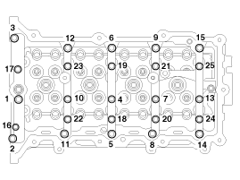
Install the camshaft bearing caps.Tighten the bolts in several passes in the specified sequence. Tightening torque — M6 bolts: 11.8 – 13.7 N·m; M8 bolts: 18.6 – 23 N·m
Be careful not to change the position or direction of the bearing caps.
Using a suitable tool, move the tensioner lever to align the tensioner bolt hole with the service hole.
Install the tensioner lever bolt (A).
Tightening Torque: 18.6 ~ 23 N·m
Remove the stopper pin from the tensioner.
Turn the crankshaft two revolutions in the normal direction of rotation (clockwise), then make sure the TDC marks of the CVVT sprockets align in a straight line with the cylinder head surface.