Engine Mechanical System
Engine and Transaxle Assembly Repair Procedures
In this manual: Engine Mechanical System
31steps
~186min
4/5difficulty
Done 0 of 31
Removal
|
|
- Remove the engine cover (A).
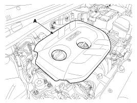

- To prevent damage, remove the engine cover at room temperature.
- To prevent damage to the engine cover, do not disconnect the front and rear mounting points at the same time.
- Disconnect the battery terminals (A). Disconnect the negative terminal first. Tightening torque: (+) terminal: 7.8 ~ 9.8 N·m; (-) terminal: 3.9 ~ 5.9 N·m
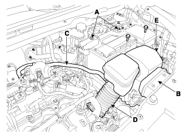
- Remove the air cleaner assembly.
- Remove the air duct (B).
Tightening torque: 7.8 ~ 9.8 N·m
- Disconnect the breather hose (C).
- Disconnect the air intake hose (D) and remove the air cleaner assembly (E). Tightening torque: Hose clamp bolt: 2.9 ~ 4.9 N·m; Air cleaner mounting bolts: 7.8 ~ 9.8 N·m
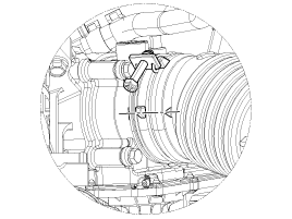
- Install the air intake hose so that the clamp plate is aligned with the hose plug.
- Install the air intake hose so that the center of the hose mark is aligned with the throttle body rib.
- Remove the air duct (B).
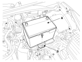
- Remove the battery (A) after removing the battery mounting bracket (B).
Tightening torque: 9.8 ~ 14.7 N·m
- Disconnect the ECM connectors (A) and remove the ECM (B).
Tightening torque: 9.8 ~ 11.8 N·m
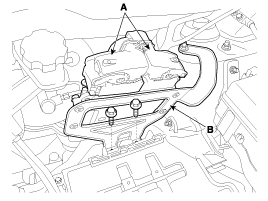
- Loosen the battery "+" cable bracket mounting bolt (A) and remove the battery tray (B).
Tightening torque: 9.8 ~ 14.7 N·m
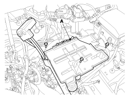
- Remove the lower cover (A).
Tightening torque: 7.8 ~ 11.8 N·m
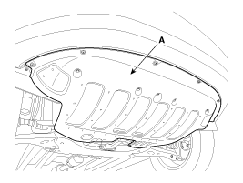
- Loosen the drain plug and drain the engine coolant. Remove the radiator cap to drain the coolant faster. (Refer to Cooling System in this group)
- Disconnect the upper radiator hose (A).
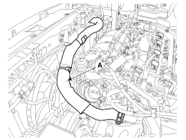
- Disconnect the radiator lower hose (A).
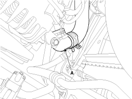
- Recover the refrigerant, then remove the high pressure line and low pressure line (A). (Refer to Heating, Ventilation and Air Conditioning - Air Conditioning System)
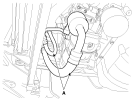
- Disconnect the transaxle wiring harness connectors, control cable and hoses from the transaxle. (Refer to Manual Transmission System) (Refer to Automatic Transmission section)
- Disconnect the heater hoses (A).
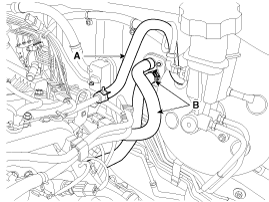
When installing the heater hoses, install them as shown in the illustrations.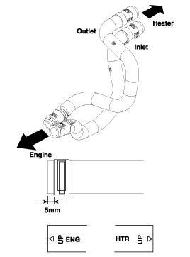
- Disconnect the wiring connectors and harness clips, then remove the wiring and protector from the cylinder head and intake manifold.
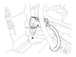
- OCV (Oil Control Valve) Intake Connector (A)
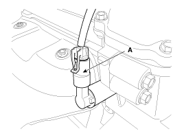
- OCV (Oil Control Valve) Exhaust Connector (A)
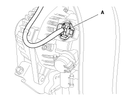
- Alternator Connector (A)
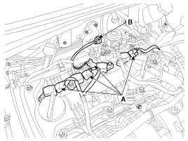
- Ignition Coil Connectors (A), Fuel Pump Connector (B).
- CMPS (Camshaft Position Sensor) Intake Connector (A)
- CMPS (Camshaft Position Sensor) Exhaust Connector (B)
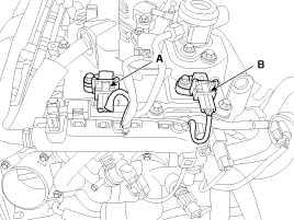
- Injector Connectors (A)
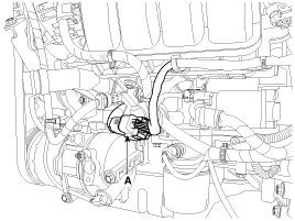
- Front and/or Rear Heated Oxygen Sensor (HO2S) Connectors (A)
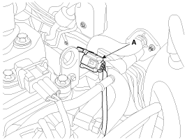
- Condenser Connector (A)
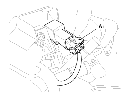
- PCSV (Purge Control Solenoid Valve) Connector (A)
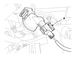
- ECTS (Engine Coolant Temperature Sensor) Connector (A)
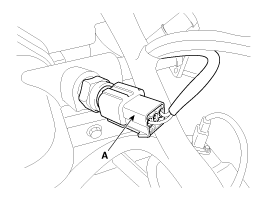
- VIS (Variable Intake System) Connector (A)
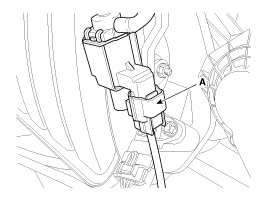
- MAPS (Manifold Absolute Pressure Sensor) and IATS (Intake Air Temperature Sensor) Connector (A)
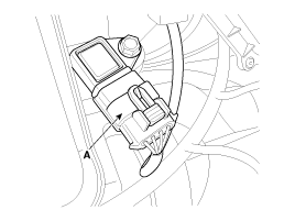
- ETC (Electronic Throttle Control) Connector (A)
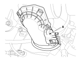
- OCV (Oil Control Valve) Intake Connector (A)
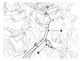
- Disconnect the "+" cable (A) and front connector (B).
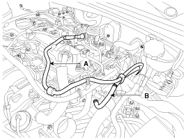
- Disconnect the fuel hose (A) and PCSV (Purge Control Solenoid Valve) hose (B).
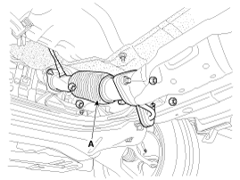
- Remove the front muffler (A).
Tightening torque: 39.2 ~ 59 N·m
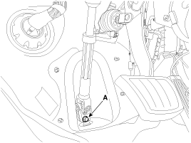
- Remove the steering universal joint mounting bolt (A). (Refer to Steering System - Steering Gear Box)
- Remove the front wheels. (Refer to Suspension System)
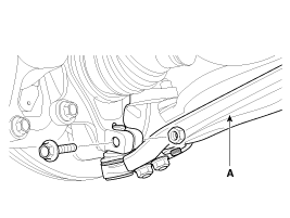
- Remove the lower arms (A). (Refer to Suspension System - Front Lower Arm)
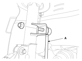
- Remove the stabilizer bar links (A). (Refer to Suspension System - Front Stabilizer Bar)
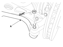
- Remove the tie rod ends (A). (Refer to Steering System - Steering Gear Box)
- Disconnect the drive shafts (A) from the hub assemblies. (Refer to Drive Shaft and Axle - Front Drive Shaft)
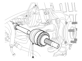
- Remove the roller rod bracket (A). Tightening torque: Nut (B): 107.9 ~ 128 N·m; Bolt (C): 49.0 ~ 64 N·m
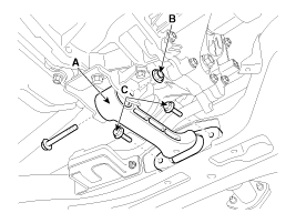
- Remove the roller rod bracket (A).
Tightening torque: 49.0 ~ 69 N·m
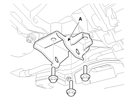
- Support the subframe (A) with a jack, then remove the subframe mounting bolts and nuts. Tightening torque: Subframe mounting bolts and nuts: 176.5 ~ 197 N·m (18.0 ~ 20.0 kgf·m, 130.2 ~ 144.7 ft-lbf)
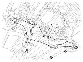

- After removing the subframe mounting bolts and nuts, the engine and transaxle assembly may drop. Support it securely with a floor jack.
- Before removing the engine and transaxle assembly, make sure all hoses and connectors are disconnected.
- Disconnect the ground line (A), then remove the engine mounting bracket (B). Tightening torque: Ground line bolt (A): 10.8 ~ 13.7 N·m; Nut (C): 78.5 ~ 98 N·m; Bolt (D) and nuts (E): 78.5 ~ 98 N·m
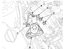
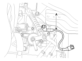
- Disconnect the ground line (A).
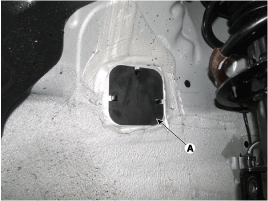
- Remove the service cover (A).
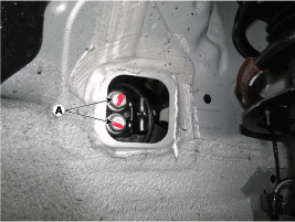
- Remove the transaxle mounting bracket bolt (A).
Tightening torque: 88.3 ~ 108 N·m
- Lower the engine and transaxle assembly (A) using a floor jack, then remove the engine and transaxle assembly by raising the vehicle.
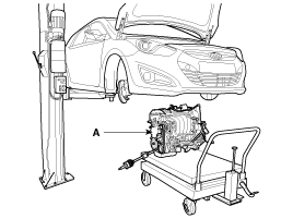
When removing the engine and transaxle assembly, be careful not to damage surrounding parts or body components.
Installation
Installation is the reverse of removal.
|
Test yourself
A quick Hyundai Tucson LM quiz: every answer comes with an explanation and a link to the manual page.
Was this page helpful?