Engine removal is not necessary for this procedure.
Use fender covers to avoid damaging painted surfaces.
To avoid damage, carefully disconnect the wiring connectors by holding the connector body.
Label all wires and hoses to avoid incorrect connection.
Disconnect the negative battery terminal. (Refer to Engine and Transaxle Assembly in this group)
Remove the air cleaner assembly. (Refer to Engine and Transaxle Assembly in this group)
Remove the right front wheel. (Refer to Suspension System - "Wheel")
Remove the under cover. (Refer to Engine and Transaxle Assembly in this group)
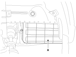
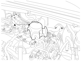
Remove the right side cover (A).
Remove the engine cover. (Refer to Engine and Transaxle Assembly in this group)
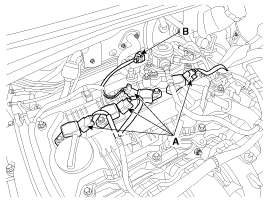
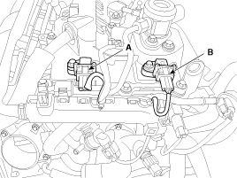
Disconnect the wiring connectors and wiring clamps, then remove the wiring and protectors from the cylinder head cover.
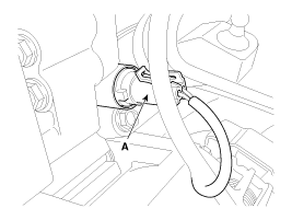
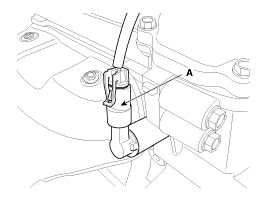
OCV (Oil Control Valve) Intake Connector (A)
OCV (Oil Control Valve) Exhaust Connector (A)
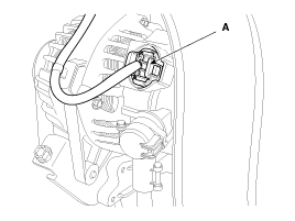
Alternator Connector (A)
Ignition coil connectors (A)
Fuel pump connector (B)
CMPS (Camshaft Position Sensor) Intake Connector (A)
CMPS (Camshaft Position Sensor) Exhaust Connector (B)
Remove the high pressure pump (A).
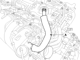
Disconnect the PCV (Positive Crankcase Ventilation) hose (A).
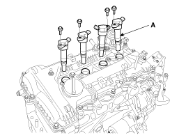
Remove the ignition coils (A).
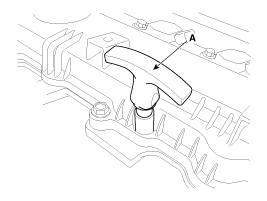
Remove the engine oil level sensor (A).
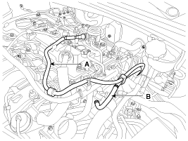
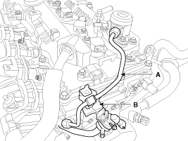
Disconnect the fuel hose (A) and PCSV (Purge Control Solenoid Valve) hose (B).
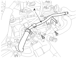
Remove the vacuum hose (A).
Remove the high pressure fuel line (A) and the PCSV (Purge Control Solenoid Valve) bracket (B). (Refer to Engine Control/Fuel System - "High Pressure Fuel Pump")
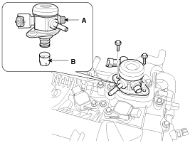
Remove the high pressure fuel pump (A) and the roller tappet (B). (Refer to Engine Control/Fuel System - "High Pressure Fuel Pump")
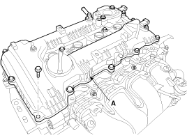
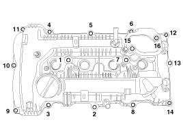
Remove the cylinder head cover (A).
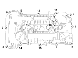
Loosen the bolts in the sequence shown.
Drain the engine oil and remove the oil pan. (Refer to Lubrication System in this group)
Remove the engine mount support bracket.
Install a jack to the edge of the lower block.
Place a wooden block between the bottom of the block and the jack.
Be careful not to damage the oil filter.
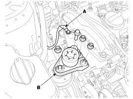
Disconnect the engine ground line (A).
Remove the engine mount bracket (B).
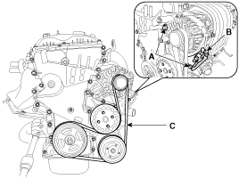
Remove the drive belt.
Loosen the generator mounting bolts (A).
Loosen the tension by turning the tension adjusting bolt (B) counterclockwise.
Remove the drive belt (C).
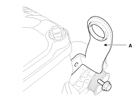
Remove the front engine mount (A).
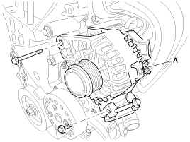
Remove the generator (A). (Refer to Engine Electrical System - "Generator")
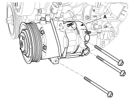
Remove the A/C compressor (A). (Refer to Heating, Ventilation and Air Conditioning - "A/C Compressor").
Remove the water pump pulley (A).
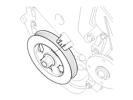
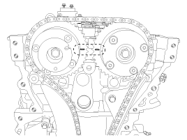
Set the No. 1 cylinder to TDC (top dead center) on the compression stroke.
Turn the crankshaft pulley and align its groove with the alignment mark on the timing chain cover.
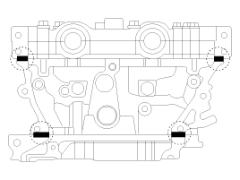
Make sure the TDC marks on the intake and exhaust CVVT sprockets are in a straight line on the cylinder head surface, as shown in the illustration. Otherwise, rotate the crankshaft one full turn (360°) or more.
Do not turn the crankshaft pulley counterclockwise.
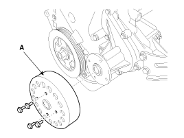
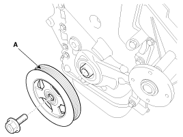
Remove the crankshaft damper pulley (A).
Do not press on the pulley or apply excessive force to prevent deformation of the rubber part.
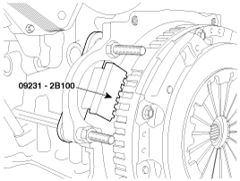
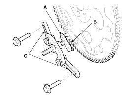
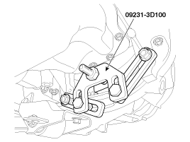
There are two methods for holding the ring gear when removing the crankshaft damper pulley.
Install SST (09231-2B100) to hold the ring gear after removing the starter.
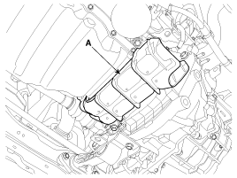
Install SST (09231-3D100) to hold the ring gear after removing the service cover.
Remove the air guard (A).
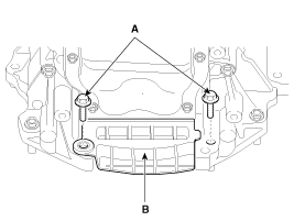
Remove the two transaxle mounting bolts (A) and remove the service cover (B) at the bottom of the oil pan.
Adjust the length of the holder (A) so that the holder grooves engage the ring gear teeth (B) in the closest position.
Adjust the angle and length of the links (C) so that the two transaxle mounting bolts can be secured in the original installation holes.
Install the SST using the two transaxle mounting bolts. Tighten the holder and link bolts and nuts securely.
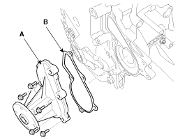
Remove the water pump assembly (A) with the gasket (B).
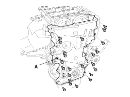
Remove the timing chain cover (A) by carefully prying at the gaps between the cylinder head and cylinder block.
Be careful not to damage the contact surfaces of the cylinder block, cylinder head and timing chain cover.
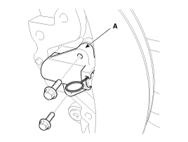
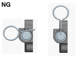
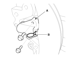
Remove the timing chain tensioner (A).
Do not reuse a removed tensioner.
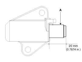
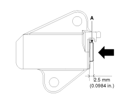
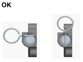
If the tensioner must be reused, remove the tensioner, fully extend the piston (A), press the piston (A) fully in, and then install the stopper pin. At this time, the tensioner locking pin must be inserted in the same way as when the product was first delivered from the factory.
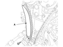
Remove the timing chain tensioner arm (A).
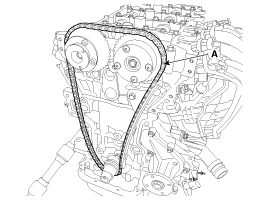
Remove the timing chain (A).
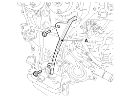
Remove the timing chain guide (A).
Inspection
Sprockets, Chain Tensioner, Chain Guide, Chain Tensioner Arm
Inspect the CVVT sprocket and crankshaft sprocket for abnormal wear, cracks, or damage. Replace if necessary.
Inspect the tensioner arm and chain guide for excessive wear, cracks, or damage. Replace if necessary.
Make sure the tensioner piston moves smoothly.
Inspect the tensioner pulley for excessive oil leakage, abnormal rotation or vibration. Replace if necessary.
Inspect the belt for maintenance and abnormal wear of the ribs. Replace if necessary.
Check the pulleys for vibration during rotation and oil or dust buildup on the V-groove. Replace if necessary.
Drive Belt, Tensioner Pulley, Pulley
Do not bend, twist or turn the timing belt inside out.
Do not allow the timing belt to contact oil, water or steam.
Installation
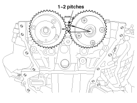
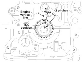
With the timing chain removed, the TDC marks on the intake and exhaust CVVT sprockets are slightly rotated from the TDC position, as shown.
Turn the crankshaft clockwise (approximately 1-2 teeth) from the TDC position (the crankshaft alignment pin (A) is at an angle of approximately 3° to the vertical centerline of the engine) as the intake CVVT sprocket rotates from the TDC position.
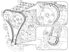
Install the timing chain without slack between the crankshaft sprocket and the intake CVVT sprocket.
The timing marks on each sprocket must align with the timing marks (colored links) of the timing chain when installing the timing chain.
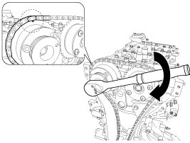
Install the timing chain on the exhaust CVVT sprocket without slack by rotating the CVVT assembly clockwise.
The installation mark on the exhaust CVVT sprocket must align with the timing mark (colored link) of the timing chain when installing the timing chain.
Press the timing chain links onto the exhaust CVVT sprocket to prevent the sprocket from rotating.
Install the automatic timing chain tensioner (A) and remove the stopper pin (B).
Tightening torque: 9.8 ~ 11.8 N·m
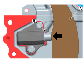
When reinstalling the tensioner, check the ratchet function after removing the locking pin by pushing the tensioner arm (A) fully in, as shown below.
When fully retracted, the tensioner arm (A) and tensioner body (B) must not interfere with each other.
After rotating the crankshaft two turns in the normal direction (clockwise when viewed from the front), make sure the TDC marks on the intake and exhaust CVVT sprockets are aligned with the upper surface of the cylinder head.
Install the timing chain cover.
Using a gasket scraper, remove all old sealant from the gasket surfaces.
The sealant contact areas on the chain cover and mating parts (cam carrier, cylinder head, cylinder block and oil pan) must be free of harmful foreign material, oil, dust and moisture. Spray cleaner onto the surface and wipe with a clean cloth.
Before installing the timing chain cover, apply liquid gasket to the joint between the cam carrier, cylinder head and cylinder block. Bead width: 3.0 - 5.0 mm (0.11 - 0.20 in). Sealant: Threebond 1217H or equivalent.
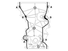
After applying liquid sealant to the timing chain cover, assemble the cover within 5 minutes after applying the sealant. Apply a continuous bead of sealant to prevent any oil leakage path.
Sealant bead width
Whole section: 2.5 ~ 3.5 mm (0.10 ~ 0.14 in)
Section A: 4.5 ~ 5.5 mm (0.18 ~ 0.22 in)
Section B: 8.0 ~ 9.0 mm (0.32 ~ 0.35 in)
Sealant: Threebond 1217H or equivalent
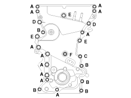
Install the timing chain cover. Use the dowel pins on the cylinder block and the holes in the timing chain cover to locate the timing chain cover in the correct position.
Tightening torque
Bolts (A, B): 18.6 ~ 24 N·m
Bolt (C): 19.6 ~ 24 N·m
Bolts (D, E): 39.2 ~ 49 N·m
Bolt (F): 9.8 ~ 11.8 N·m
Do not reuse the seal bolts (C, F).
Do not start the engine or perform a pressure test for 30 minutes after installing the timing chain cover.
Install the water pump assembly (A) with a gasket (B).
Tightening torque: 9.8 ~ 11.8 N·m
If necessary, replace the front oil seal.
Apply engine oil to the lip of the new oil seal.
Remove foreign material from the lip of the oil seal.
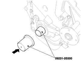
Install the front oil seal using SST (09231-2E000).
Do not press on the pulley or apply excessive force to prevent deformation of the rubber part.
There are two methods to hold the ring gear when installing the crankshaft damper pulley.
Install SST (09231-2B100) to hold the ring gear after removing the starter.
Install SST (09231-3D100) to hold the ring gear after removing the service cover.
Remove the air guard (A).
Remove the two transaxle mounting bolts (A) and remove the service cover (B) at the bottom of the oil pan.
Adjust the length of the holder (A) so that the holder grooves engage the ring gear teeth (B) in the closest position.
Adjust the angle and length of the links (C) so that the two transaxle mounting bolts can be secured in the original installation holes.
Install the SST using the two transaxle mounting bolts. Tighten the holder and link bolts and nuts securely.
Install the water pump pulley (A).
Tightening torque: 9.8 ~ 11.8 N·m
Install the A/C compressor (A). (Refer to Heating, Ventilation and Air Conditioning - "A/C Compressor").
Install the front engine mount bracket (A).
Tightening torque: 34.3 to 39 N·m
Install the drive belt.
Temporarily assemble the generator (A).
Install the drive belt (B).
Adjust the tension by turning the tension adjusting bolt (A) clockwise. (Refer to Engine Electrical System - "Generator") Belt tension New belt: 637.4 ~ 735.5 N (65 ~ 75 kgf, 143.3 ~ 165.3 lbf) Used belt: 441.3 ~ 539.4 N (45 ~ 55 kgf, 99.2 ~ 121.3 lbf)
Tighten the generator mounting bolts to the specified torque. Torque M10 bolt: 29.4 ~ 41 N·m M8 bolt: 21.6 ~ 32 N·m
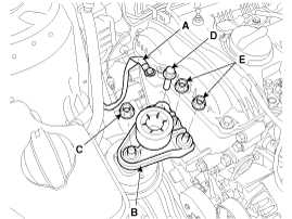
Install the engine mount bracket.
Install the engine mount bracket (B). Torque Nut (C): 78.5 ~ 98 N·m Bolt (D) and nuts (E): 78.5 ~ 98 N·m
Connect the engine ground line (A).
Torque: 10.8 ~ 13.7 N·m
Remove the jack from the lower block.
Install the oil pan. (Refer to Lubrication System in this group)
Install the cylinder head cover.
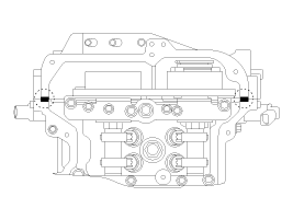
Remove the hardened sealant on the cylinder head cover and the gap between the timing chain cover and the camshaft holder before installing the cylinder head cover.
Apply engine oil to the seal lip on the cover and to the outer surface of the spark plug tubes.
After applying sealant to the gap between the timing chain cover and the camshaft holder, assemble within 5 minutes. Bead width: 2.0 ~ 3.0 mm (0.08 ~ 0.12 in). Sealant: Threebond 1217H or equivalent.
Install the cylinder head cover (A), tightening the bolts in several passes in the specified sequence. Torque Step 1: 3.9 ~ 5.9 N·m Step 2: 7.8 ~ 9.8 N·m
Do not reuse the cylinder head cover gasket.
Before installing the cylinder head cover, make sure the cover gasket is seated in the gasket groove of the cover.
Do not start the engine or perform a leak test within 30 minutes after installing the cylinder head cover.
Install the high pressure fuel pump (A) and the roller tappet (B). (Refer to Engine Control/Fuel System - "High Pressure Fuel Pump")
Tightening torque: 12.7 - 14.7 N·m
Install the high pressure fuel line (A) and the PCSV (Purge Control Solenoid Valve) bracket (B). (Refer to Engine Control/Fuel System - "High Pressure Fuel Pump") Torque High pressure fuel line nuts: 26.5 ~ 32 N·m Bracket bolt: 9.8 ~ 11.8 N·m
Install the vacuum hose (A).
Tightening torque: 9.8 ~ 11.8 N·m
Connect the fuel hose (A) and the PCSV (Purge Control Solenoid Valve) hose (B).
Install the oil level sensor (A).
Install the ignition coils (A).
Tightening torque: 9.8 ~ 11.8 N·m
Connect the PCV (Positive Crankcase Ventilation) hose (A).
Install the high pressure pump (A).
Install the wiring and protectors on the cylinder head cover, then connect the wiring connectors and wiring clamps.
OCV (Oil Control Valve) Intake Connector (A)
OCV (Oil Control Valve) Exhaust Connector (A)
Alternator Connector (A)
Ignition coil connectors (A)
Fuel pump connector (B)
CMPS (Camshaft Position Sensor) Intake Connector (A)
CMPS (Camshaft Position Sensor) Exhaust Connector (B)
Install the engine cover. (Refer to Engine and Transaxle Assembly in this group)
Install the right side cover (A).
Tightening torque: 3.9 ~ 5.9 N·m
Install the under cover. (Refer to Engine and Transaxle Assembly in this group)
Install the right front wheel. (Refer to Suspension System - "Wheel")
Connect the negative battery terminal. (Refer to Engine and Transaxle Assembly in this group)
Install the air duct and cleaner assembly. (Refer to Engine and Transaxle Assembly in this group)
Add all required fluids and check for leaks. Connect the GDS. Check for DTCs, note them, and clear them. Recheck.
Fill the engine with engine oil.
Clean the battery terminal posts and cable clamps, then assemble.
Inspect for fuel leaks.
After assembling the fuel line, turn the ignition ON (do not crank the engine) so the fuel pump operates for approximately two seconds to pressurize the fuel line.
Repeat this procedure two or three times, then check all fuel line connections for leaks.
?
Test yourself
A quick Hyundai Tucson LM quiz: every answer comes with an explanation and a link to the manual page.