Connecting Rod Big End Bearing Insert/Crankpin Wear Inspection
- Remove the connecting rod big end (see Connecting Rod Removal).
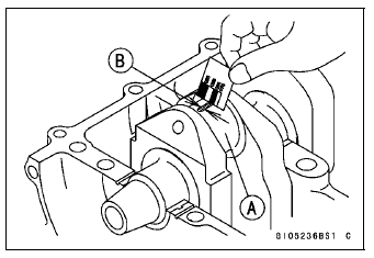
- Cut strips of plastigage to crankpin width. Place a strip on the crankpin parallel to the crankshaft installed in the correct position.
- Tighten the connecting rod big end nuts to the specified torque (see Connecting Rod Installation).
NOTE
Do not move the connecting rod and crankshaft during clearance measurement.
Remove the connecting rod big end again, measure each clearance between the bearing insert and crankpin [A] using plastigage (press gauge) [B].
NOTICE
After measurement, replace the connecting rod bolts and nuts.
Connecting Rod Big End Bearing Insert/Crankpin Clearance
Standard: 0.030  0.060 mm
(0.0012  0.0024 in.)
Service Limit: 0.10 mm (0.0039 in.)
If the clearance is within the standard, no bearing replacement is required.
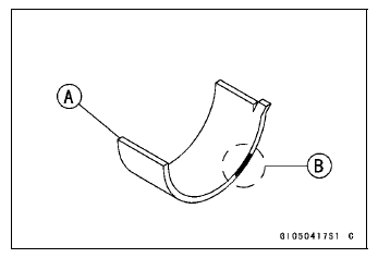
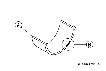
If the clearance is between 0.061 mm (0.0024 in.) and the service limit (0.10 mm, 0.0039 in.), replace the bearing inserts [A] with inserts painted blue [B]. Check insert/ crankpin clearance with the plastigage. The clearance may exceed the standard slightly, but it must not be less than the minimum in order to avoid bearing seizure.
If the clearance exceeds the service limit, measure the diameter of the crankpins.
Crankpin Diameter
Standard: 34.484  34.500 mm
(1.3576  1.3583 in.)
Service Limit: 34.47 mm (1.3571 in.)
- If any crankpin has worn past the service limit, replace the crankshaft with a new one.
- If the measured crankpin diameters [C] are not less than the service limit, but do not coincide with the original diameter markings [D] on the crankshaft, make new marks on it.
Crankpin Diameter Marks
None 34.484  34.492 mm (1.3576

1.3580 in.)
 34.493
 34.500 mm (1.3580
 1.3583 in.)
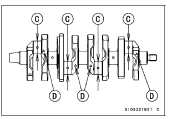
 : Crankpin Diameter Marks (“” or
No Mark)
- Measure the connecting rod big end inside diameter, and mark each connecting rod big end in accordance with the inside diameter.
- Tighten the connecting rod big end nuts to the specified torque (see Connecting Rod Installation).
NOTE
The mark already on the big end should almost coincide with the measurement.
Connecting Rod Big End Inside Diameter Marks
None 37.500  37.508 mm
(1.4764  1.4767 in.)
 37.509
 37.516 mm (1.4767
 1.4770 in.)
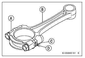
Big End Cap [A] Connecting Rod [B] Weight Mark, Alphabet [C] Diameter Mark [D] (“” or No Mark)
- Select the proper bearing insert [A] in accordance with the combination of the connecting rod and crankshaft coding.
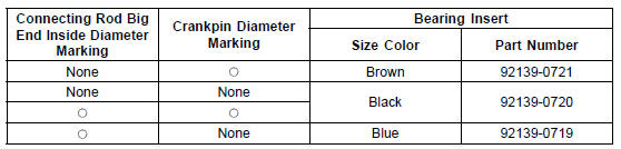
- Install the new inserts in the connecting rod and check insert/crankpin clearance with the plastigage.
Test yourself
A quick Kawasaki Ninja ZX-10R quiz: every answer comes with an explanation and a link to the manual page.