Electrical System
Crankshaft Sensor Peak Voltage Inspection
In this manual: Electrical System
~1min read
NOTE
- Be sure the battery is fully charged.
- Using the peak voltage adapter [A] is more reliable way to determine the condition of the crankshaft sensor than crankshaft sensor internal resistance measurements.
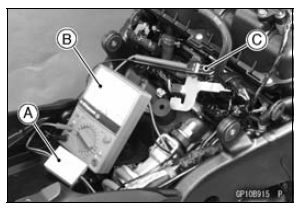
- Disconnect the crankshaft sensor lead connector (see Crankshaft Sensor Removal).
- Set the hand tester [B] to the DC 10 V range, and connect it peak voltage adapter.
Special Tools - Hand Tester: 57001-1394 Peak Voltage Adapter: 57001-1415 Type: KEK-54-9-B
- Connect the adapter to the terminals of the crankshaft sensor lead connector [C].
Connections: Crankshaft Sensor Lead Connector Peak Voltage Adapter Hand Tester Y lead ← R lead → (+) BK lead ← BK lead → (–)
- Turn the engine stop switch to run position.
- Turn the ignition switch to ON.
- Pushing the starter button, turn the engine 4 ∼ 5 seconds with the transmission in neutral to measure the peak voltage.
- Repeat the measurements 5 times or more times.
Crankshaft Sensor Peak Voltage Standard: 1.9 V or more
If the reading is less than the standard, inspect the crankshaft sensor (see Crankshaft Sensor Inspection).
Test yourself
A quick Kawasaki Ninja ZX-10R quiz: every answer comes with an explanation and a link to the manual page.
Was this page helpful?