Suspension System
Troubleshooting
In this manual: Suspension System
38steps
~228min
4/5difficulty
Done 0 of 38
Troubleshooting
Vehicle Inspection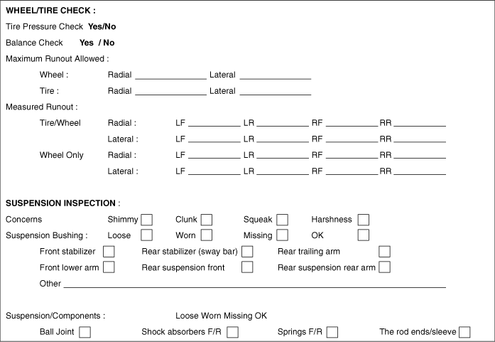
| Symptom | Suspect area | Remedy (Refer to page) |
| Squeak or grunt noise from front suspension, more likely to occur in cold weather or on rough roads or when turning. | Front Stabilizer Bar | Under these conditions, the noise is acceptable. |
| Knock noise from front suspension, occurs when turning and when not turning. | Loose front struts or shock absorbers. | Check for loose nuts or bolts. Tighten to specification. |
| Knock noise from rear suspension, occurs when shifting from reverse to drive. | Loose or Damaged Rear Suspension Components | Inspect rear suspension components for looseness or damage. Repair or install new components as necessary. |
| Click or pop noise from front suspension, more noticeable on rough roads or bumps. | Worn or damaged ball joints. | Install a new lower arm as necessary. |
| Click or pop noise occurs when turning the vehicle. | Worn or damaged ball joints. | Install a new lower arm as necessary. |
| Click or clunk noise occurs when accelerating while turning. | Damaged or worn Birfield joint. | Repair or install a new Birfield joint as necessary. Refer to Group DS - Propeller Shaft. |
| Front suspension noise - squeak, creak or rattle - mainly occurs on bumps or rough roads. | Steering components Loose or bent front struts or shock absorbers Damaged spring or spring seats Worn or damaged arm bushings Worn or damaged stabilizer bar bushings or links |
Go to Diagnostic Procedure A. |
| Squeak or scrape - front strut noise occurring on rough roads or when turning the vehicle. | Uneven seating surface between strut insulator and body panel, burrs around strut insulator bolts and insulator bolt mounting holes | Repair or install new parts as necessary. |
| Rear suspension noise - squeak, creak or rattle - mainly occurs on bumps or rough roads. | Loose or bent rear shock absorbers Damaged spring or spring seats Worn or damaged suspension arm bushings |
Go to Diagnostic Procedure B. |
| Shudder - occurs during acceleration from low speed or when stopping. | Rear axle assembly incorrectly positioned Damaged or worn front suspension components |
Inspect axle mounts and rear suspension for damage or wear. Repair as necessary. Check for loose stabilizer bar, damaged or loose strut/strut bushings, or loose or worn ball joints. Inspect tie rod for wear or damage. Repair or install new components as necessary. |
| Shimmy - most noticeable during coasting/deceleration - also stiff steering. | Excessive Positive Caster | Check wheel alignment angles. Adjust as necessary. |
| Tire noise - hum/moan at constant speed. | Abnormal wear | Rotate the tire and check tire wear. Install a new tire as necessary. Inspect suspension components for damage or wear. Perform wheel alignment. |
| Tire noise - noise tone decreases as vehicle speed decreases. | Unbalanced tire | Balance the tire and road test. Install a new tire as necessary. |
| Tire noise - ticking, changes with speed. | Nail puncture or stone in tire tread | Inspect the tire. Repair or replace as necessary. |
| Wheel and tire - vibration and noise directly related to vehicle speed, independent of acceleration, coasting or deceleration. | Damaged or worn tire | Go to Diagnostic Procedure C. |
| Tire shake or shimmy - occurs at lower speeds. | Damaged wheel bearings | Rotate the wheel and check for abnormal play or roughness in the wheel bearing. If necessary, adjust or install new wheel bearings. Refer to Group DS - Front/Rear Axle. |
| Damaged wheel | Inspect the wheel for damage. If necessary, install a new wheel. | |
| Damaged or worn suspension components | Inspect the suspension components for wear or damage. Repair as necessary. | |
| Loose wheel nuts | Check the wheel nuts. Tighten to specification. |
|
| Damaged or uneven tire wear | Rotate the tire and check for abnormal wear or damage. If necessary, install a new tire. | |
| Tire shimmy or vibration - occurs at low speeds | Wheel/tire out of balance | |
| Uneven tire wear | Check the tires for abnormal wear. If necessary, install a new tire. | |
| Excessive radial runout of wheel or tire | Perform a radial runout test on the wheel and tire. If necessary, install a new tire. |
|
| Worn or damaged wheel studs or elongated stud holes | Inspect the wheel studs and wheels. If necessary, install new components. |
|
| Excessive lateral runout of wheel or tire | Perform a lateral runout test on the wheel and tire. Inspect the wheel, tire and hub. If necessary, repair or install new components. |
|
| Foreign material between brake disc and hub. | Clean the mounting surfaces of the brake disc and hub. Refer to Group DS - Front/Rear Axle. |
|
| Shake or shudder at high speed - occurs at high speeds. | Excessive wheel hub runout Damaged or worn tires Damaged or worn wheel bearings Worn or damaged suspension or steering linkage Brake disc or drum imbalance |
Go to Detailed Test D. |
| Drift left or right | Tires Steering linkage Alignment Base brake system |
Go to Detailed Test E. |
| Steering Wheel | Alignment Steering linkage Front lower arm ball joint |
Go to Detailed Test F. |
| Tracks incorrectly | Rear suspension Caster |
Go to Detailed Test G. |
| Harsh ride | Front strut and spring assembly Rear shock absorber and spring assembly |
Go to Detailed Test H. |
| Excessive Noise | Front or rear stabilizer bar components Springs Suspension components Shock absorbers |
Go to Detailed Test I. |
| Abnormal tire wear | Tire or unbalanced wheels Tire inflation Strut Alignment |
Go to Detailed Test J. |
| Vibration | Wheel/tire Front drive axle shaft(s) Steering system Strut and spring assembly Strut and spring mount Front lower arm ball joint Front lower arm bolt bushing Stabilizer bar bushings Wheel hubs and bearings Rear suspension arms and bushings |
Go to Detailed Test K. |
| Vehicle leans | Tire/wheel Vehicle load Suspension components Incorrect ground clearance |
Inflate tires to specification. Redistribute load as necessary. Visually inspect the suspension system. If necessary, adjust ride height. |
| Poor steering return | High steering knuckle torque Alignment |
Go to Detailed Test E. |
DIAGNOSTIC PROCEDURE A: FRONT SUSPENSION NOISE
| CONDITIONS | DETAILS/RESULTS/ACTIONS |
| A1. VEHICLE ROAD TEST | |
|
|
| A2. CHECK STEERING SYSTEM | |
|
|
| A3. CHECK FRONT SHOCK ABSORBER/STRUT | |
|
|
| A4. CHECK FRONT SPRINGS | |
| Inspect the front spring and front spring seats/brackets for wear or damage. ● Are the front springs or spring seats/brackets worn or damaged? → YES If necessary, repair or install new components. Check the system for normal operation. → NO Go to A5. |
|
| A5. CHECK STABILIZER BAR | |
|
|
DIAGNOSTIC PROCEDURE B: REAR SUSPENSION NOISE
| CONDITIONS | DETAILS/RESULTS/ACTIONS |
| B1. VEHICLE ROAD TEST | |
|
|
| B2. CHECK REAR SHOCK ABSORBER/STRUT | |
|
|
| B3. CHECK REAR COIL SPRINGS | |
| Inspect the rear leaf springs and rear spring mounts/brackets for wear or damage. ● Are the rear springs or spring seats/brackets worn or damaged? → YES Repair or install new components as necessary. Verify the system operates normally. → NO Go to B4. |
|
| B4. CHECK TRAILING ARMS | |
|
|
DIAGNOSTIC PROCEDURE C: WHEEL AND TIRE
| CONDITIONS | DETAILS/RESULTS/ACTIONS | ||||
| C1. ROAD TEST VEHICLE | |||||
● Is there vibration and noise? → YES Go to C2. → NO Wheel and tire are OK. Diagnose other suspected systems. |
|||||
| C2. CHECK FRONT WHEEL BEARINGS | |||||
| Check the front hub bearings. Refer to "Wheel Bearing Check" (Refer to Group DS - Front Axle). ● Are the wheel bearings OK? → YES Go to C3. → NO Inspect the wheel bearings. Adjust or repair as necessary. Verify the system operates normally. |
|||||
| C3. CHECK TIRES | |||||
|
|||||
| C4. TIRE ROTATION DIAGNOSIS | |||||
|
|||||
| C5. CHECK TIRE RADIAL RUNOUT | |||||
| Measure the radial runout of the wheel and tire assembly. Typical total radial runout specification is 1.15 mm (0.059 in). ● Is the radial runout within specification? → YES Go to C8. → NO Go to C6. |
|||||
| C6. CHECK WHEEL RADIAL RUNOUT | |||||
| Measure the radial runout of the wheel. Typical total radial runout specification is 1.14 mm (0.045 in). ● Is the radial runout within specification? → YES Install a new tire. Verify the system operates normally. → NO Go to C7. |
|||||
| C7. CHECK HUB/BRAKE DISC OR DRUM RUNOUT OR STUD CIRCLE RUNOUT | |||||
| Measure the pilot or stud circle runout. Typical radial runout specification: ● Pilot runout - less than 0.15 mm (0.006 in) ● Stud circle runout - less than 0.38 mm (0.015 in) ● Is the radial runout within specification? → YES Install a new wheel. Verify the system operates normally. → NO Repair or install new components as necessary. |
|||||
| C8. CHECK TIRE LATERAL RUNOUT | |||||
| Measure the lateral runout of the wheel and tire assembly. Typical total lateral runout specification is 2.5 mm (0.098 in). ● Is the lateral runout within specification? → YES Disc and tire are OK. Diagnose other suspected systems. → NO Go to C9. |
|||||
| C9. CHECK WHEEL LATERAL RUNOUT | |||||
| Measure the lateral runout of the wheel. Typical total lateral runout specification is 1.2 mm (0.047 in). ● Is the lateral runout within specification? → YES Install a new tire. Verify the system operates normally. → NO Go to C10. |
|||||
| C10. CHECK FLANGE FACE LATERAL RUNOUT | |||||
| Measure the lateral runout of the flange face. Typical lateral runout specification: ● Hub/brake disc - less than 0.13 mm (0.005 in) ● Is the lateral runout within specification? → YES Install a new wheel. Verify the system operates normally. → NO Repair or install new components as necessary. |
|||||

DIAGNOSTIC PROCEDURE D:
| CONDITIONS | DETAILS/RESULTS/ACTIONS |
| D1. CHECK FRONT WHEEL BEARING ROUGHNESS | |
|
|
| D2. CHECK FRONT WHEEL BEARING END PLAY | |
| Check the front wheel bearing end play. ● Is the end play within specification? → YES Go to D3. → NO Adjust or repair as necessary. Verify the system operates normally. |
|
| D3. MEASURE FRONT WHEEL LATERAL AND RADIAL RUNOUT | |
| Measure the lateral runout and radial runout of the front wheels. Go to Detailed Test C. ● Are the measurements within specification? → YES Go to D4. → NO If necessary, install new wheels and balance the assembly. Verify the system operates normally. |
|
| D4. MEASURE FRONT WHEEL LATERAL RUNOUT | |
| Measure the lateral runout of the front tires. Go to Detailed Test C. ● Is the runout within specification? → YES Go to D5. → NO If necessary, install new tires and balance the assembly. Verify the system operates normally. |
|
| D5. MEASURE FRONT WHEEL RADIAL RUNOUT | |
| Measure the radial runout of the front tires. Go to Detailed Test C. ● Is the runout within specification? → YES Balance the front wheel and tire assembly. If any tire cannot be balanced, install a new tire. Verify the system operates normally. → NO Go to D6. |
|
| D6. MATCH TIRE AND WHEEL ASSEMBLY | |
| Mark the high point of runout on the tire and on the wheel. Lower the assembly and rotate the tire 180 degrees (halfway) relative to the wheel. Inflate the tire and measure the radial runout. ● Is the runout within specification? → YES Balance the assembly. Verify the system operates normally. → NO If the high point is not within 101.6 mm (4 inches) of the first high point on the tire, go to D7. |
|
| D7. MEASURE WHEEL FLANGE RUNOUT | |
| Remove the tire and mount the wheel on a balancing stand. Measure the runout on both wheel flanges. Go to Detailed Test C. ● Is the runout within specification? → YES Locate and mark the low point on the wheel. Install the tire so that the high point on the tire matches the low point on the wheel. Balance the assembly. Verify the system operates normally. If the condition persists, go to D8. → NO Install a new wheel. Check the runout on the new wheel. If the new wheel is within specification, locate and mark the low point. Install the tire so that the high point on the tire matches the low point on the wheel. Balance the assembly. Verify the system operates normally. If the condition persists, go to D8. |
|
| D8. CHECK FOR VIBRATION FROM THE FRONT OF THE VEHICLE | |
| Rotate the front wheel and tire assembly on a balancing stand while the vehicle is raised on a lift. Feel for vibration in the front fender or while seated in the vehicle. ● Is there vibration? → YES If necessary, replace a known good wheel and tire assembly. Verify the system operates normally. → NO Check the driveline components. Verify the system operates normally. |
|
DIAGNOSTIC PROCEDURE E: PULL TO LEFT OR RIGHT
| CONDITIONS | DETAILS/RESULTS/ACTIONS |
| E1. CHECK THE TIRES | |
| Inspect the tires for excessive wear or damage. ● Are the tires excessively worn or damaged? → YES Install new tires. → NO Go to E2. |
|
| E2. CHECK THE STEERING LINKAGE | |
|
|
| E3. CHECK VEHICLE ALIGNMENT | |
|
|
| E4. BRAKE DIAGNOSIS | |
| Apply the brakes while driving. ● Does the vehicle pull or grab during braking? → YES Refer to Group BR - Specifications. → NO If the steering wheel is centered, the vehicle is operating normally. If the steering wheel is off center, go to Detailed Test F. |
|
DIAGNOSTIC PROCEDURE F: STEERING WHEEL OFF CENTER
| CONDITIONS | DETAILS/RESULTS/ACTIONS |
| F1. CHECK FOR CLEAR VISION | |
| Position the vehicle on an alignment rack. ● Is the clear vision within specification? → YES Go to F2. → NO Adjust the clear vision to specification. |
|
| F2. CHECK STEERING COMPONENTS | |
|
|
DIAGNOSTIC PROCEDURE G: INCORRECT TRACKING
| CONDITIONS | DETAILS/RESULTS/ACTIONS |
| G1. CHECK THE ROLLER | |
| Position the vehicle on an alignment rack. ● Is the roller within specification? → YES Go to G2. → NO Replace bent or damaged components. |
|
| G2. CHECK THE REAR SUSPENSION | |
|
|
DIAGNOSTIC PROCEDURE H: HARSH RIDE
| CONDITIONS | DETAILS/RESULTS/ACTIONS |
| H1. CHECK THE FRONT SHOCK ABSORBER | |
|
|
| H2. CHECK THE REAR SHOCK ABSORBERS | |
| Inspect the rear shock absorbers for oil leaks or damage. ● Are the rear shock absorbers leaking? → YES Install new rear shock absorbers. → NO The vehicle is operating normally. Go to SYMPTOM CHART. |
|
DIAGNOSTIC PROCEDURE I: EXCESSIVE NOISE
| CONDITIONS | DETAILS/RESULTS/ACTIONS |
| I1. CHECK THE SUSPENSION | |
|
|
| I2. CHECK THE COIL SPRING AND TORSION BARS | |
| Inspect the springs and stabilizer bars for damage. ● Are the springs or stabilizer bars damaged? → YES Install new springs and/or stabilizer bars. → NO Go to I3. |
|
| I3. CHECK FRONT SUSPENSION | |
| Inspect the front suspension components for excessive wear or damage. ● Are the front suspension components worn or damaged? → YES Install new front suspension components. → NO The vehicle is OK. Go to SYMPTOM TROUBLESHOOTING. |
|
DIAGNOSTIC PROCEDURE J: ABNORMAL TIRE WEAR
| CONDITIONS | DETAILS/RESULTS/ACTIONS |
| J1. CHECK TIRES | |
|
|
| J2. UNEVEN TIRE WEAR | |
| Inspect the tires for feathering. ● Do the tires have a feathered pattern? → YES Align the vehicle. Install new tires if wear is severe. → NO Go to J3. |
|
| J3. CHECK FOR CUPPED TIRES | |
| Inspect the tires for cupping or bulging. ● Are the tires cupped or bulging? → YES Balance and rotate the tires. → NO The vehicle is OK. Go to SYMPTOM TROUBLESHOOTING. |
|
DIAGNOSTIC PROCEDURE K: VIBRATION
| CONDITIONS | DETAILS/RESULTS/ACTIONS |
| K1. ROAD TEST | |
| Drive the vehicle at the speed at which the customer reported the vibration. ● Is there a vibration? → YES Go to K2. → NO The vehicle is OK. Go to SYMPTOM TROUBLESHOOTING. |
|
| K2. CHECK TIRES | |
|
|
| K3. CHECK WHEEL BEARINGS | |
| Rotate the tires by hand to check the wheel bearings for roughness. ● Is the front hub bearing OK? → YES Go to K4. → NO If necessary, install new front hub bearings. Refer to Group Ds - Front Axle. |
|
| K4. TIRE/WHEEL BALANCE | |
| Check the tire/wheel balance. ● Are the tires balanced? → YES Go to K5. → NO If necessary, balance the tires and wheels. |
|
| K5. MEASURE RUNOUT | |
| For each wheel position measurement, locate and mark the following points. - High point of total radial runout of tire/wheel assembly - High point of radial runout of wheel - High point of lateral runout of wheel ● Do the runouts meet the specification? → YES Go to Tires/Wheels. → NO Go to K6. |
|
| K6. REPLACE WHEELS AND TIRES | |
|
|
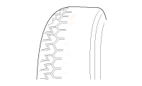
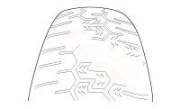
Noise, vibration and harshness problems in the wheels/tires are directly related to vehicle speed and are generally not affected by acceleration, coasting or deceleration. In addition, an unbalanced wheel and tire may vibrate at more than one speed. Vibration affected by engine speed, or eliminated by shifting the transmission to Neutral, is not related to the tire and wheel. Generally, tire and wheel vibrations felt through the steering wheel are related to the front tire and wheel assembly. Vibrations felt in the seat or floor are related to the rear tire and wheel assembly. This may help initially isolate the problem to the front or rear. Pay special attention to the tires and wheels. There are several symptoms that may be caused by a damaged or worn tire and wheel. Perform a careful visual inspection of the tires and wheel assemblies. Slowly rotate the wheels and watch for signs of lateral or radial runout. Refer to the tire wear chart to determine the tire wear conditions and actions.
| WHEEL AND TIRE DIAGNOSIS | ||
| Rapid Wear in Center | Rapid Wear on Both Shoulders | Wear on One Shoulder |
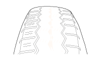 |
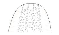 |
 |
|
|
|
| Partial Wear | Feathered Edge | Wear Pattern |
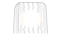 |
 |
 |
|
|
|
Test yourself
A quick Kia Cadenza VG Owner's Manual quiz: every answer comes with an explanation and a link to the manual page.
Was this page helpful?