Crankshaft Repair procedures
Disassembly
Shut off the high voltage circuit.
(Refer to Engine Mechanical System - “High Voltage Shut off Procedure”)
Remove the engine assembly from the vehicle.
(Refer to Engine and Transaxle Assembly - “Engine and Transaxle Assembly”)
Remove the dual clutch transmission
.(Refer to Dual Clutch Transmission (DCT) - "Dual Clutch Transmission Assembly")
Install the engine to engine stand for disassembly.
Remove the intake manifold.
(Refer to Intake and Exhaust System - "Intake Manifold")
Remove the exhaust manifold.
(Refer to Intake and Exhaust System - "Exhaust Manifold")
Remove the hybrid starter generator (HSG).
(Refer to Hybrid Motor System - "Hybrid Starter Generator (HSG)")
Remove the timing chain.
(Refer to Timing System - “Timing Chain”)
Remove the Cylinder head assembly.
(Refer to Cylinder Head Assembly - "Cylinder Head")
Remove the fly wheel.
(Refer to Cylinder Block - "Fly Wheel")
Remove the thermostat.
(Refer to Cooling System - "Thermostat")
Remove the water pump assembly.
(Refer to Cooling System - "Water Pump")
Remove the A/C compressor.
(Refer to Heating, Ventilation Air conditioning -"Compressor")
Remove the oil filter.
(Refer to Lubrication System - "Engine Oil")
Remove the oil screen.
(Refer to Lubrication System - "Oil Pan")
Remove the piston and connecting rod assemblies.
(Refer to Cylinder Block - "Piston and Connecting Rod")
Check the crankshaft main bearing oil clearance.
Check the crankshaft end play.
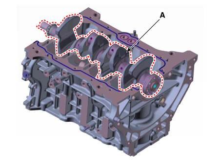
Lift the crankshaft (A) out of the engine, being careful not to damage journals.
Inspection
Pilot Bearing
Inspect the pilot bearing.
Check if the pilot bearing (A) is damaged visually.

Check if there is noise by rotating the inner shell (A) of pilot bearing.

If a damage or noise is found, then replace the crankshaft with the pilot bearing.
Crankshaft
Check the crankshaft bearing oil clearance.
To check main bearing-to-journal oil clearance, remove the lower crankcase and lower bearings.
Clean each main journal and bearing with a clean shop towel.
Place one strip of plastigage across each main journal.
Reinstall the lower crankcase and lower bearings, and then tighten the main bolts.
Tightening torque :
[17.7 - 22 N·m + [88 - 92°]
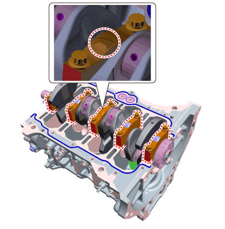
Remove the lower crankcase and lower bearings.
Measure the width of the plastigage at its widest point.
Oil clearance :
Standard :
0.006 - 0.024 mm (0.0002 - 0.0009 in)
Limit :
0.018 - 0.044 mm (0.0007 - 0.0017 in.)

If the plastigage measures too wide or too narrow, remove the upper and lower bearing and then install a new bearings with the same color mark. Recheck the oil clearance.
If the plastigage shows the clearance is still incorrect, try the next larger or smaller bearing. Recheck the oil clearance.
Crankshaft Bore Identification Mark
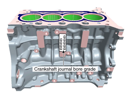
Letters are been stamped on the block as a mark for the size of each of the 5 main journal bores.
Use them, and the numbers or bar stamped on the crank (marks for main journal size), to choose the correct bearings.
Cylinder Block Specifications
Class Mark Inside Diameter a A 52.000 - 52.006 mm
(2.0472 - 2.0475 in)b B 52.006 - 52.012 mm
(2.0475 - 2.0477 in)c C 52.012 - 52.018 mm
(2.0477 - 2.0480 in)
Crankshaft Journal Identification Mark
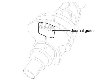
Crankshaft Specifications
Class Mark Outside Diameter Of Journal I 1 47.954 - 47.960 mm
(1.8880 - 1.8882 in.)II 2 47.948 - 47.954mm
(1.8877 - 1.8880 in.)III 3 47.942 - 47.948 mm
(1.8875 - 1.8877 in.)
Crankshaft Bearing Identification Mark
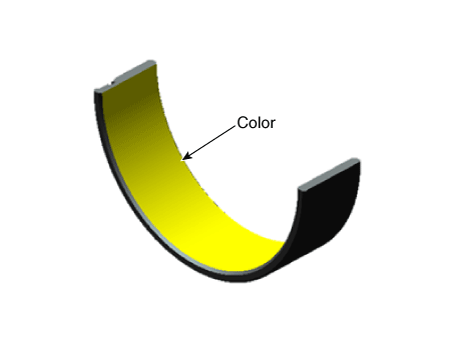
Crankshaft Bearing Specifications
Class Mark Crankshaft Main Bearing Thickness A Blue 2.026 - 2.029 mm
(0.0797 - 0.0798 in)B Black 2.023 - 2.026 mm
(0.0796 - 0.0797 in)C None 2.020 - 2.023 mm
(0.0795 - 0.0796 in)D Green 2.017 - 2.020 mm
(0.0794 - 0.0795 in)E Yellow 2.014 - 2.017 mm
(0.0793 - 0.0794 in)Select a crankshaft bearing using the selection chart.
Selection Chart For Crankshaft Bearings
Assembling Classification Of Bearing Crankshaft Bore Identification Mark 0(A) 1(B) 2(C) Crankshaft Identification Mark I (1) E (Yellow) D (Green) C (None) II (2) D (Green) C (None) B (Black) III (3) C (None) B (Black) A (Blue)
Check crankshaft end play.
Using a dial indicator, measure the thrust clearance while prying the crankshaft back and forth with a screwdriver.
If the end play is greater than maximum, replace the center bearing.
End play Standard: 0.07 - 0.25 mm (0.0028 - 0.0098 in.)
Inspect main journals and crank pins.
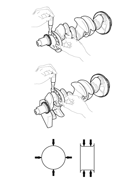
Using a micrometer, measure the diameter of each main journal and crank pin.
Main journal diameter :
47.942 - 47.960- mm (1.88748 - 1.88819 in.)
Crank pin diameter :
68.954 - 38.972 mm (1.53362 - 1.53433 in.)
Reassembly
Check if the pilot bearing (A) is installed in the crankshaft when replacing the crankshaft or short engine.
If being not installed, be sure to install the pilot bearing (A).
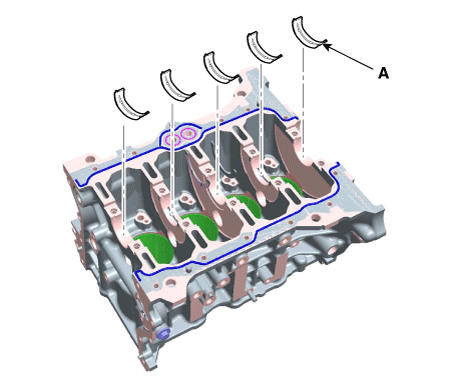
Install the crankshaft main bearings.
Align the bearing claw with the groove of the cylinder block, and push in the 5 upper bearings (A).
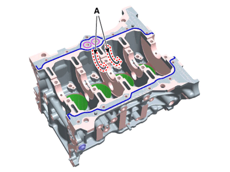
Install the thrust bearings.
Install the 2 thrust bearings (A) on both sides of the No.3 journal of the cylinder block with the oil groove facing out.
Place the crankshaft (A) on the cylinder block.
Install the main bearing caps and tighten the cap bolts.
Apply a light coat of engine oil on the threads of the bolts. Tighten all the bolts with the specified torque in numerical order first, then tighten all the bolts with the specified angle in numerical order.
Tightening torque :
[17.7 - 22 N·m] + [88 - 92°]
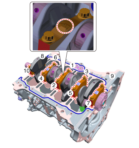
Check that the crankshaft turns smoothly.
Check the crankshaft end play.
Install the other parts in the reverse order of disassembly.