Cylinder Block Repair procedures
Disassembly
Shut off the high voltage circuit.
(Refer to Engine Mechanical System - “High Voltage Shut off Procedure”)
Remove the engine assembly from the vehicle.
(Refer to Engine and Transaxle Assembly - “Engine and Transaxle Assembly”)
Remove the dual clutch transmission.
(Refer to Dual Clutch Transmission (DCT) - "Dual Clutch Transmission Assembly")
Install the engine to engine stand for disassembly.
Remove the intake manifold.
(Refer to Intake and Exhaust System - "Intake Manifold")
Remove the exhaust manifold.
(Refer to Intake and Exhaust System - "Exhaust Manifold")
Remove the hybrid starter generator (HSG).
(Refer to Hybrid Motor System - "Hybrid Starter Generator (HSG)")
Remove the timing chain.
(Refer to Timing System - “Timing Chain”)
Remove the Cylinder head assembly.
(Refer to Cylinder Head Assembly - "Cylinder Head")
Remove the fly wheel.
(Refer to Cylinder Block - "Fly Wheel")
Remove the thermostat.
(Refer to Cooling System - "Thermostat")
Remove the water pump assembly.
(Refer to Cooling System - "Water Pump")
Remove the A/C compressor.
(Refer to Heating, Ventilation Air conditioning -"Compressor")
Remove the oil filter.
(Refer to Lubrication System - "Engine Oil")
Remove the oil screen.
(Refer to Lubrication System - "Oil Pan")
Remove the piston and connecting rod assemblies.
(Refer to Cylinder Block -"Piston and Connecting")
Remove the Crankshaft.
(Refer to Cylinder Block -"Crankshaft")
Remove the knock sensor.
(Refer to Engine Control / Fuel System - "Knock Sensor")
Remove the crankshaft position sensor (CKPS).
(Refer to Engine Control / Fuel System - "Crankshaft Position Sensor (CKPS)")
Remove the oil pressure switch.
(Refer to Lubrication System - "Oil Pressure Switch")
Remove the water jacket insert.
(Refer to Cylinder Block - "Water Jacket Insert")
Remove the piston cooling oil jet (A).
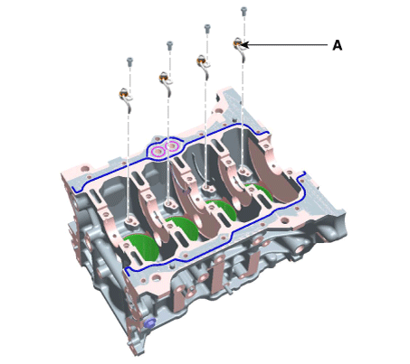
Inspection
Remove gasket material.
Using a gasket scraper, remove all the gasket material from the top surface of the cylinder block.
Clean cylinder block
Using a soft brush and solvent, thoroughly clean the cylinder block.
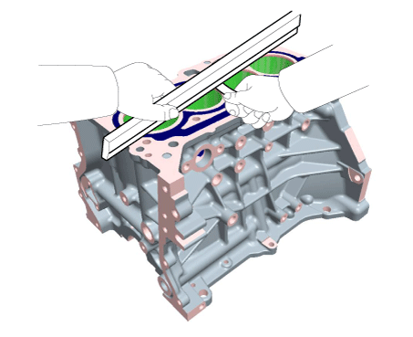
Inspect top surface of cylinder block for flatness.
Using a precision straight edge and feeler gauge, measure the surface contacting the cylinder head gasket for warpage.
Flatness of cylinder block gasket surface :
Standard :
Less than 0.05 mm (0.0020 in.) for total area
Less than 0.02 mm (0.0008 in.) for a section of 100 mm (3.9370 in.) X 100 mm (3.9370 in.)
Inspect the cylinder bore
Visually check the cylinder for vertical scratches.
If deep scratches are present, replace the cylinder block.
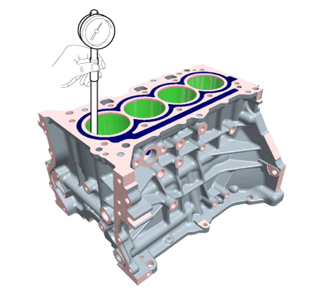
Inspect the cylinder bore diameter.
Using a cylinder bore gauge, measure the cylinder bore diameter at position in the thrust and axial direction.
Cylinder bore diameter : 72.00 - 72.03 mm (2.8346 - 2.8358 in.)
Check the cylinder bore size code on the cylinder block side surface.
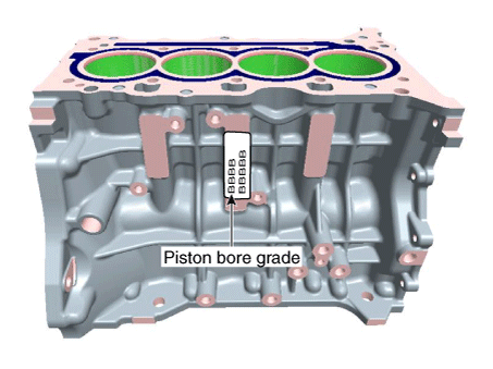
Cylinder Bore Inner Diameter
Size Code Inside Diameter A 72.00 - 72.01 mm
(2.8346 - 2.8350 in.)B 72.01 - 72.02 mm
(2.8350 - 2.8354 in)C 72.02 - 72.03 mm
(2.8354 - 2.8358 in.)
Reassembly
Install the piston cooling oil jet (A).
Tightening torque : 8.8 - 10,8 N·m
Assemble the remaining parts in the reverse order of disassembly.