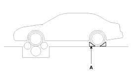
Drive the vehicle onto the speedometer tester. Use wheel chocks (A) as appropriate.
Check that the speedometer reading is within the standard values.
[km/h]
Speed (km/h)
Tolerance (km/h)
20
+3,0 +0,5
40
+5,8 +3,3
60
+6,2 +3,7
80
+7,1 +4,1
100
+7,5 +4,5
120
+7,9 +4,9
140
+9,4 +5,9
160
+10,4 +6,9
180
+11,4 +7,9
200
+12,4 +8,9
220
+13,4 +9,9
240
+14,4 +10,9
[mile/h]
Speed (mile/h)
Tolerance (mile/h)
20
+3,0 +1,0
40
+4,9 +2,9
60
+6,8 +4,8
80
+7,5 +5,0
100
+8,2 +5,2
120
+8,7 +5,7
140
+9,2 +6,2
160
-
Connect GDS to the diagnostic connector or install a tachometer.
With the engine running, compare the tester reading with the tachometer data. Replace the tachometer if the tolerance is exceeded.
Engine Speed (rpm)
Gasoline
Diesel
Tolerance (rpm) Max. 8000 rpm
Tolerance (rpm) Max. 6000 rpm
1000
± 100
± 100
2000
± 100
± 100
3000
± 100
± 100
4000
± 100
± 100
5000
± 100
± 100
6000
± 100
± 100
7000
± 100
8000
± 100
Disconnect the fuel level sender connector from the fuel level sender.
Remove the fuel pump assembly.
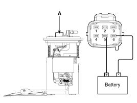
Check the fuel pump motor operation by connecting the power (No. 4) and ground (No. 5) connector of the fuel pump (A).
No.
Description
1
Fuel Level Sensor Signal
2
-
3
Fuel Level Sensor Ground
4
-
5
Fuel Pump Motor (+)
6
Fuel Pump Motor (-)
Turn the ignition switch OFF and disconnect the (-) battery cable.
Remove the fuel pump assembly.
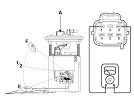
Using an ohmmeter, measure the resistance between terminals 1 and 3 of the sensor connector (A) at each float level.
No.
Description
1
Fuel Level Sensor Signal
2
-
3
Fuel Level Sensor Ground
4
-
5
Fuel Pump Motor (+)
6
Fuel Pump Motor (-)
Also check that the resistance changes smoothly as the float moves from "E" to "F".
Position
Resistance (Ω)
Capacity (L)
E
197 ~ 203
3,7
1/2
64,2 ~ 68,2
26,7
Fuel Level Sender Gauge (F)
6 ~ 10
52,6
If the resistance at any level is out of specification, replace the fuel level sensor as an assembly.
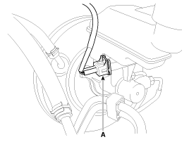
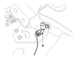
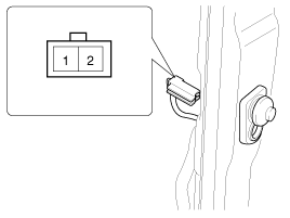
Disconnect the connector (A) from the switch located on the brake fluid reservoir.
Check for continuity between switch terminals 1 and 2 while pressing the switch (float) rod down.
Ignition switch ON
Release the parking brake.
Disconnect the connector from the brake fluid level warning switch.
Ground the harness-side connector.
Check that the warning lamp illuminates.
Check for continuity between the terminal and the switch body with the switch ON (lever pulled).
Check that there is no continuity between the terminal and the switch body with the switch OFF (lever released). If continuity does not meet the specification, replace the switch or check the ground connection.
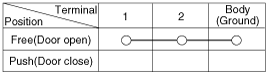
Disconnect the connector from the switch.
Check the circuit between the terminals for continuity.
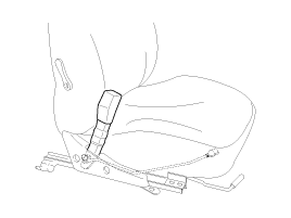
Seat Belt Status
Continuity
Fastened
Non-continuity (∞ Ω)
Unfastened
Continuity (Ω)
Tachometer, Fuel Level Gauge, Fuel Level Sensor, Brake Fluid Level Warning Lamp, Brake Fluid Level Warning Lamp Switch, Parking Brake Switch. Parking brake switch (A) is a pull type. It is located under the parking brake lever. To adjust, move the switch mounting up and down with the parking brake lever fully released. Door Switch: Remove the door switch and check continuity between the terminals. Seat Belt Switch: Seat belt warning lamp. With the ignition ON, check that the lamp illuminates.
Seat Belt Status
Indicator Lamp
Fastened
OFF
Unfastened
ON
Diagnosis Using GDS
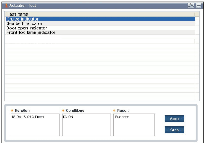
The cluster can be quickly diagnosed for defects using GDS. GDS can perform forced actuator control, input/output value monitoring and self-diagnosis.
Select the model and "BCM".
Select "Cluster Module" for inspection.
Select "Input/Output Control" to check the current data of the instrument cluster.
If you are going to forcibly check each module data operation, select "Active Test".
To check the DTC of each module, select "DIAGNOSTIC TROUBLE CODES".
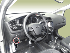
Connect the GDS cable to the data link connector (DLC) on the driver's side, lower instrument panel, then turn on the GDS power.
Select the model and "BCM".
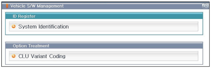
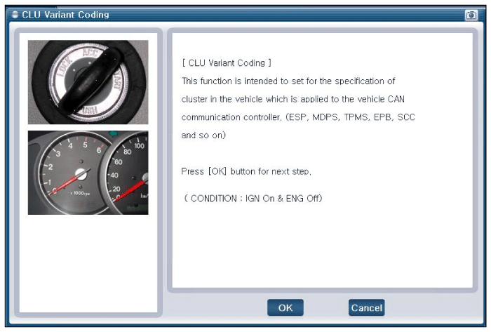
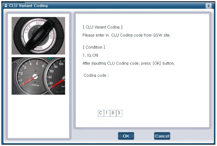
Select Variant Coding mode to perform.
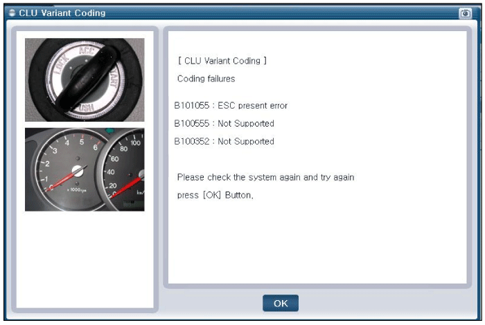
If diagnostic trouble codes occur when performing variant coding, check the CLU installation status and then retry the CLU Variant Coding.
CLU Variant Coding: After replacing the cluster with a new one, perform the "Variant Coding" procedure.
Removal
Disconnect the negative (-) battery terminal.
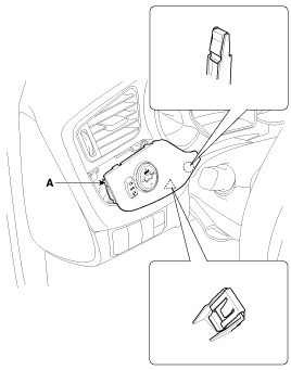
Using a screwdriver or trim tool, remove the [LH] decorative trim (A).
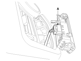
Disconnect the connector of the power outside rearview mirror switch (A).
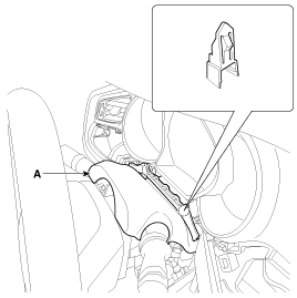
Using a screwdriver or a trim removal tool, remove the upper steering column shroud panel (A).
Using a screwdriver or trim tool, remove the instrument panel cylinder cover (A).
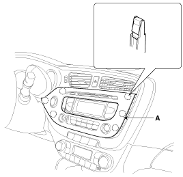
Using a screwdriver or a trim remover, remove the center fascia panel (A).
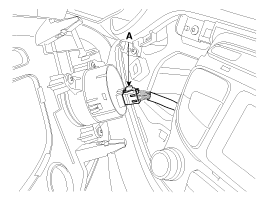
Disconnect the connector of the start/stop button (A).
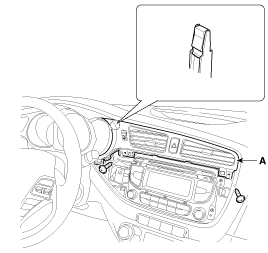
Loosen the mounting screws and remove the center air duct (A).
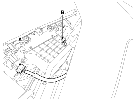
Disconnect the hazard warning switch connector (A) and the ESC OFF switch connector (B).
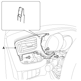
Loosen the mounting screws and remove the side air duct [LH] (A).
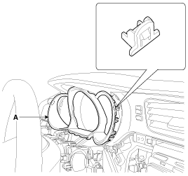
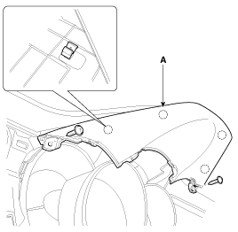
After loosening the mounting screws, remove the upper cluster facia panel (A).
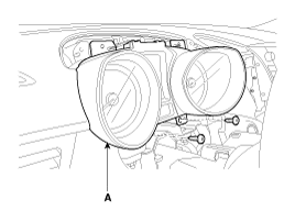
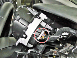
Remove the cluster (A) after loosening the screws and disconnecting the connector (B).
Installation
Install the cluster into the emergency panel.
Install the instrument panel upper cover, side ventilation duct [LH], cowl cover, decorative trim [LH] and center ventilation duct.
Install the instrument panel cluster cover, center facia panel, cover panel and lower airbag panel.
?
Test yourself
A quick Kia Cee'd quiz: every answer comes with an explanation and a link to the manual page.