Manual Transmission
Control Cable
In this manual: Manual Transmission
26steps
~156min
4/5difficulty
Done 0 of 26
Components and Component Location
Components
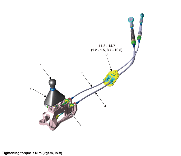
| 1. Knob 2. Boot 3. Shift Lever Assembly |
4. Shift Cable 5. Select Cable 6. Clip |
Repair Procedures
Inspection
- Check that the shift lever operates correctly when shifting (1st, 2nd, 3rd, 4th, 5th, R).
- If the gear shift feels stiff, adjust the length of the control cable again. (Refer to Manual Transaxle Control System - "Control Cable")
Adjustment
- Move the shift lever to 4th gear.
- Remove the control cable (B) from the control shaft after removing the lock pins (A).
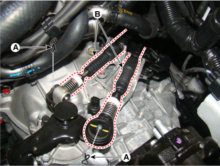
- Pull the holder (A) in the "P" direction, then pull the lock (B) in the "F" direction.

- Install the lock pins (A).

- Press the lock (C) after installing the control cable to the control shaft.
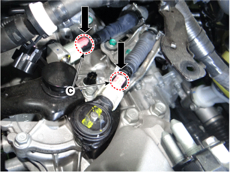
Removal
- Move the shift lever to the 4th gear position. Raise the battery and battery tray.
- Remove the battery and battery tray. G 1.0 T-GDI KAPPA (Refer to Engine Electrical System - "Battery")
- Remove the control cable.
- Remove the control cable from the control shaft after removing the lock pins (A).
- Remove the control cable (B) from the bracket (C).
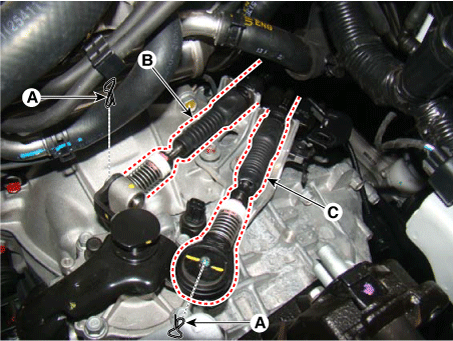
- Remove the handle (A) by pulling it in the direction of the arrow.

- Remove the floor console assembly. (Refer to Body - "Floor Console Assembly")
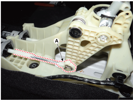
- Remove the stopper pin (A), then disconnect the select cable from the shift lever pin.
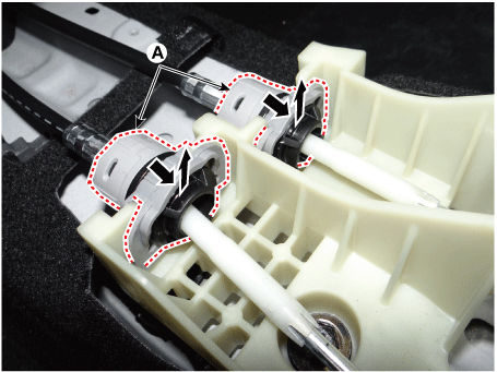
- Remove the cable connectors (A) from the shift lever.
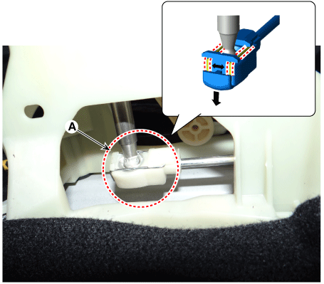
- Remove the shift lever (A).
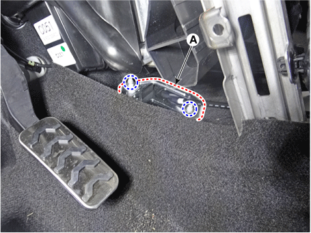
- Remove the shift cable bracket (A) after loosening the nuts. Then remove the shift cable by pulling it toward the passenger compartment.
Installation
- Install the shift cable bracket by tightening the nuts (A).
Tightening torque: 11.8–14.7 N·m
- Install the shift cable (A).
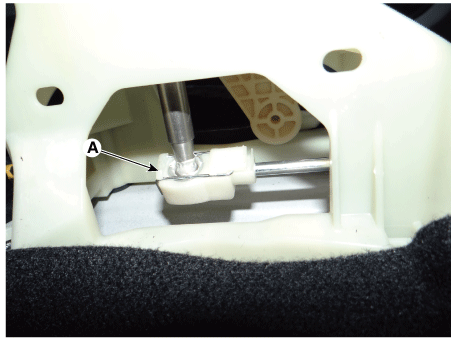
- Install the cable sockets (A).
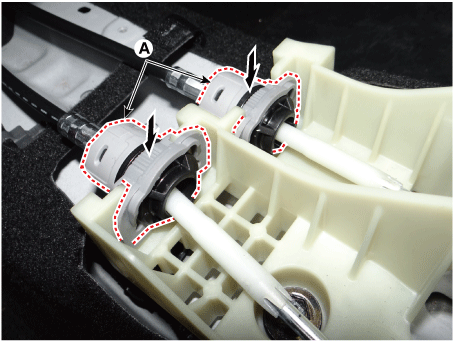
- Install the select cable onto the lever pin, then insert the lock pin (A).
- Make sure the shift lever and control shaft are in the "4" position, then install the 4th lock pin.
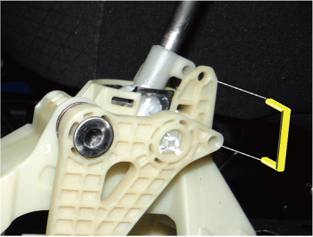
- Install the control cable.
- Pull the holder (A) in the "P" direction, then pull the lock (B) in the "F" direction.
- Install the lock pins (A) after installing the control cable (B).
- Press the lock (C) after installing the control cable to the control shaft.
- Pull the holder (A) in the "P" direction, then pull the lock (B) in the "F" direction.
- Remove the 4th lock pin (A).
- Install the floor console assembly. (Refer to Body - Floor Console Assembly)
- Install the handle (A) by pressing it in the direction of the arrow.

- Install the battery and battery tray. G 1.0 T-GDI KAPPA (Refer to Engine Electrical System - "Battery")
Test yourself
A quick Kia Picanto JA quiz: every answer comes with an explanation and a link to the manual page.
Was this page helpful?