Drive Shaft (Tripod Joint) Disassembly/Assembly
1. Disassemble in the order indicated in the table.
2. Assemble in the reverse order of disassembly.
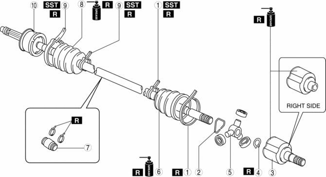
Boot band (transaxle side)
(See Boot Band (Transaxle Side) Disassembly Note.)
(See Boot Band (Transaxle Side) Assembly Note.)
Clip (only SKYACTIV-G 2.0)
(See Clip, Outer Ring Disassembly Note (For SKYACTIV-G 2.0).)
(See Outer Ring, Clip Assembly Note (For SKYACTIV-G 2.0).)
Outer ring
(See Outer Ring Disassembly Note (Except for SKYACTIV-G 2.0).)
(See Clip, Outer Ring Disassembly Note (For SKYACTIV-G 2.0).)
(See Outer Ring Assembly Note (Except for SKYACTIV-G 2.0).)
(See Outer Ring, Clip Assembly Note (For SKYACTIV-G 2.0))
Snap ring
(See Snap Ring, Tripod Joint Disassembly Note.)
(See Tripod Joint, Snap Ring Assembly Note.)
Tripod joint
(See Snap Ring, Tripod Joint Disassembly Note.)
(See Tripod Joint, Snap Ring Assembly Note.)
Boot
(See Boot Disassembly Note.)
(See Boot Assembly Note.)
Dynamic damper
(See Dynamic Damper Assembly Note.)
Boot band (wheel side)
(See Boot Band (Wheel Side) Disassembly Note.)
(See Boot Band (Wheel Side) Assembly Note.)
Boot
(See Boot Disassembly Note.)
(See Boot Assembly Note.)
Shaft and ball joint component
Boot Band (Transaxle Side) Disassembly Note
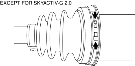
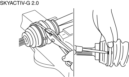
1. Pry up the boot band at the points indicated in the figure using pliers and remove the band.
Clip, Outer Ring Disassembly Note (For SKYACTIV-G 2.0)
1. Mark the outer ring and the shaft for proper assembly.
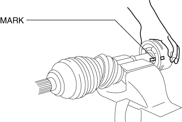
2. Remove the clip.
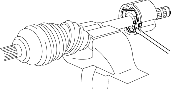
3. Remove the outer ring.
Outer Ring Disassembly Note (Except for SKYACTIV-G 2.0)1. Secure the drive shaft using a vise.
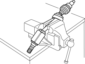
2. Tap the outer ring slightly by using a hummer and urethan bar or equivalent, and remove the outer ring from the drive shaft.
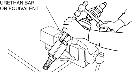
CAUTION:
Lightly tap the outer ring carefully, otherwise the tripod joint rollers could be damaged.
1. Place an alignment mark on the shaft and tripod joint.
2. Remove the snap ring using snap ring pliers.
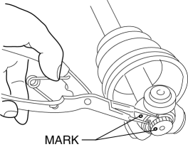
3. Remove the tripod joint from the shaft.
CAUTION:Do not try to remove the tripod joint by hitting it with a hammer. The tripod joint could be damaged.
Remove the wheel side boot only if there is any malfunction.
1. Wrap the shaft splines with tape.
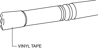
2. Remove the boot.
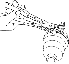
Boot Band (Wheel Side) Disassembly Note NOTE:Remove the boot band only if there is a malfunction.
1. Remove the boot band using end clamp pliers.
Boot Assembly Note NOTE:
The boot shapes on the wheel side and the differential side are different. Do not install the wrong boot by mistake.
1. Fill the inside of the new dust boot (wheel side) with grease.
NOTE:Do not touch the grease with your hand. Apply it from the tube to prevent foreign matter from entering the boot.
- Grease amount
Except for SKYACTIV-G 2.0: 96—106 g {3.4—3.7 oz}
SKYACTIV-G 2.0: 95—115 g {3.4—4.0 oz}
2. Install the boot with the drive shaft spline still wrapped with vinyl tape.
3. Remove the vinyl tape.
Boot Band (Wheel Side) Assembly Note 1. Adjust opening width A by turning the adjusting bolt of the SST.
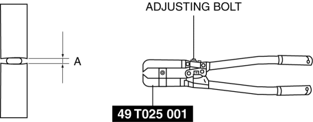
- Standard A
1.6 mm {0.063 in}
.
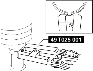
3. Verify that the boot band does not protrude from the boot band installation area.
If the boot band protrudes from the boot band installation area, replace the boot band and repeat Step 2.
4. Fill the boot with the repair kit grease.
5. Adjust opening width A of the SSTto the specification.
- Standard A
2.0 mm {0.079 in}
.
7. Verify that the boot band does not protrude from the boot band installation area.
If the boot band protrudes from the boot band installation area, replace the boot band and repeat Step 6.
1. Install the dynamic damper as shown in the figure.
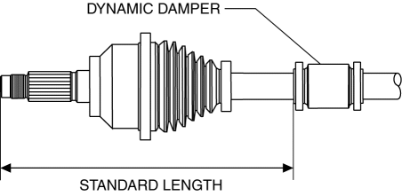
- Standard length
Except for SKYACTIV-G 2.0: 289.7—301.7 mm {11.41—11.87 in}
SKYACTIV-G 2.0: 292.7—298.7 mm {11.53—11.75 in}
2. Install the new boot band onto the dynamic damper (except for SKYACTIV-G 2.0).
Tripod Joint, Snap Ring Assembly Note1. While aligning the marks on the shaft and the tripod joint, insert the tripod joint using a bar and a hammer.
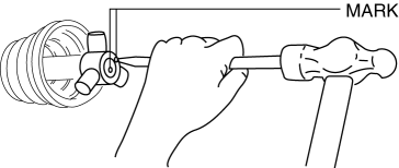
2. Insert a new snap ring using snap ring pliers.
3. Verify that the snap ring is engaged correctly in the groove of the shaft.
Outer Ring Assembly Note (Except for SKYACTIV-G 2.0)1. Fill the outer ring and boot (transaxle side) with the specified grease.
NOTE:Do not touch the grease with your hand. Apply it from the tube to prevent foreign matter from entering the boot.
- Grease amount
89—99 g {3.2—3.4 oz}
2. Secure the outer ring using a vise.
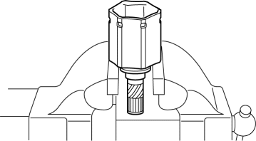
CAUTION:
Carefully perform the work when securing the outer ring to the vise, otherwise other wise the oil seal could be deformed.
3. Align the roller with the outer ring, tap the roller slightly using a hummer and urethan bar or equivalent, and install the drive shaft to the outer ring with keeping the drive shaft verticality.
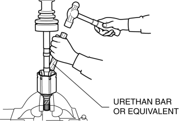
CAUTION:
Be careful that no foreign matter such as dust or dirt gets into the outer ring, otherwise the drive shaft could be damaged.
4. Set the drive shaft to the standard length.
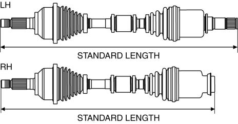
- Front drive shaft standard length
LH: 654.31—663.31 mm {25.761—26.114 in}
RH: 572.73—581.73 mm {22.549—22.902 in}
5. Release any trapped air from the boots by carefully lifting up the small end of each boot with a cloth wrapped screwdriver.
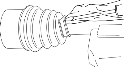
NOTE:
Verify that there is no grease leak while being careful not to damage the boot.
If the boot is damaged, it may not be possible to perform the full-length adjustment of the drive shaft.
6. Verify that the drive shaft length is within the specification under atmospheric pressure inside the boot.
If not within the specification, repeat from Step 3.
1. Fill the outer ring and boot (transaxle side) with the specified grease.
NOTE:Do not touch the grease with your hand. Apply it from the tube to prevent foreign matter from entering the boot.
- Grease amount
140—160 g {4.94—5.64 oz}
2. Align the marks, and install the outer ring on to the shaft.
3. Install the clip.
4. Set the drive shaft to the standard length.
- Front drive shaft standard length
LH: 642.7—652.7 mm {25.31—25.69 in}
RH: 572.8—582.8 mm {22.56—22.94 in}
5. Release any trapped air from the boots by carefully lifting up the small end of each boot with a cloth wrapped screwdriver.
NOTE:
Verify that there is no grease leak while being careful not to damage the boot.
If the boot is damaged, it may not be possible to perform the full-length adjustment of the drive shaft.
6. Verify that the drive shaft length is within the specification under atmospheric pressure inside the boot.
If not within the specification, repeat from Step 3.
1. Pry up the boot band at the points indicated in the figure using pliers and tighten the boot band.
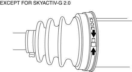
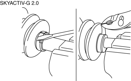
2. Verify that the boot band is installed to the boot slot securely.
Test yourself
A quick Mazda 3 quiz: every answer comes with an explanation and a link to the manual page.