Instrument Cluster Inspection
When only the front or the rear wheels are driven using a speedometer tester, the ABS or DSC may determine that the vehicle speed signal is in error and the engine cannot be stopped by the normal operation. If the engine cannot be stopped, perform an emergency engine stop operation..
1. Adjust the tire pressure to the specification.
2. Using a speedometer tester, verify that the tester reading is as indicated in the table below.
3. Verify that the speedometer reading is within the range indicated in the table.
If the speedometer does not move or the indication is not within the allowable range, inspect the PCM, ABS HU/CM (with ABS) or DSC HU/CM (with DSC), and related wiring harnesses.
If the PCM, ABS HU/CM (with ABS) or DSC HU/CM (with DSC), and related wiring harnesses are normal, replace the instrument cluster.
Speedometer tester indication (km/h) |
Allowable range (km/h) |
Speedometer tester indication (mph) |
Allowable range (mph) |
20 |
17—23 |
10 |
9—11 |
40 |
36—44 |
20 |
18—22 |
60 |
54—66 |
30 |
27—33 |
80 |
72—88 |
40 |
36—44 |
100 |
90—110 |
50 |
45—55 |
120 |
108—132 |
60 |
54—66 |
140 |
126—154 |
70 |
63—77 |
Using the M-MDS
1. Connect the M-MDS (IDS) to the DLC-2.
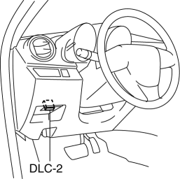
2. After the vehicle is identified, select the following items from the initialization screen of the IDS.
Select “DataLogger”.
Select “Modules”.
Select “IC”.
3. Verify that it is displayed according to the table using “SPDMTR”.
If the speedometer does not move or the indication is not within the allowable range, inspect the related wiring harnesses.
If the related wiring harnesses are normal, replace the instrument cluster.
M-MDS display |
Instrument cluster display |
60 km/h |
Speedometer gauge needle moves to approx. 60 km/h |
120 km/h |
Speedometer gauge needle moves to approx. 120 km/h |
Off |
Speedometer gauge needle moves to 0 km/h |
Tachometer CAUTION:
If the engine speed exceeds the allowable range, the engine could be damaged. Therefore, when inspecting the tachometer, do not allow the engine speed to exceed the allowable range indication on the tachometer.
1. Connect the M-MDS (IDS) to the DLC-2.
2. After the vehicle is identified, select the following items from the initialization screen of the IDS.
Select “DataLogger”.
Select “Modules”.
Select “IC”.
3. Verify that it is displayed according to the table using “TACHOMTR”.
If the tachometer does not move or the indication is not within the allowable range, inspect the related wiring harnesses.
If the related wiring harnesses are normal, replace the instrument cluster.
M-MDS display |
Instrument cluster display |
3000 RPM |
Tachometer gauge needle moves to approx. 3,000 rpm |
6000 RPM |
Tachometer gauge needle moves to approx. 6,000 rpm |
Off |
Tachometer gauge needle moves to 0 rpm |
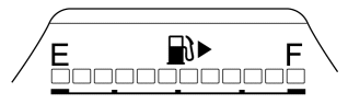
Fuel gauge
1. Connect the M-MDS (IDS) to the DLC-2.
2. After the vehicle is identified, select the following items from the initialization screen of the IDS.
Select “DataLogger”.
Select “Modules”.
Select “IC”.
3. Verify that it is displayed according to the table using “LCD_SEG”.
If any of the segments are not displayed, replace the instrument cluster.
Boost gauge
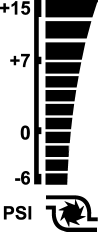
1. Connect the M-MDS (IDS) to the DLC-2.
2. After the vehicle is identified, select the following items from the initialization screen of the IDS.
Select “DataLogger”.
Select “Modules”.
Select “IC”.
3. Verify that it is displayed according to the table using “LCD_SEG”.
If any of the segments are not displayed, replace the instrument cluster.
Test yourself
A quick Mazda 3 quiz: every answer comes with an explanation and a link to the manual page.