Specifications and tightening torques
Rack and pinion steering gear mounted on the front subframe.
Height-adjustable steering wheel as standard.
Electromechanical power steering.
Power steering management
The steering is electrically assisted. The assistance to be provided is calculated based on several parameters:
- the steering torque applied,
- the wheel rotation speeds,
- the steering angle and steering speed,
- the engine speed,
- the position of the power steering servo motor rotor.
CONTROL UNIT
5-way connector pin assignment
| Pins | Assignments |
| 1 | Ground |
| 2 | Power supply via fuse 65 |
| 3 | Power supply after ignition on via fuse 24 |
| 4 | Low line of the engine CAN bus |
| 5 | High line of the engine CAN bus |
POWER STEERING COMPONENT SPECIFICATIONS AND LOCATION
TORQUE SENSOR
This inductive sensor is located near the input shaft of the steering gear housing.
It detects the deformation of the torsion bar without contact and converts it into a voltage signal.
SERVO MOTOR
The servo motor is bolted to the steering gear housing. It assists the steering torque applied by the driver and incorporates a position sensor that determines the position of the servo motor rotor.
Tightening torques (in daN.m and degrees)
 For tightening torques, also refer to the 'exploded view of parts' in the methods.
Steering wheel (*): 8.
Steering column shaft to steering gear (*): 2.
Steering column shaft to steering column tube (*): 2.
Steering column tube to dashboard cross member (*): 2.
Track rod to steering gear fastening (*): 8.
Front alignment adjustment locknut: 6.
Track rod end nut to steering knuckle (*): 6.
Steering gear housing to subframe fastening (*):
- 1st pass: 4.
- 2nd stage: 90°.
Steering gear motor control unit: 2.3.
Wheel bolts: 13
(*) Screws or nuts to be replaced after each removal.
Wiring diagrams
KEY
See explanations and how to read a diagram in the 'Electrical equipment' chapter.COMPONENTS
A91. Electromechanical control unit
A91b1. Electric power steering torque sensor
A91m1. Electric power steering servo motor
F55/3. Fuse box 3, 9 times
F55/3f24. Fuse 24
F55/9. Fuse box 9
F55/9f65. Fuse 65
N68. Electric power steering control unit
N68x1. Connector 1, power steering control unit
N68x2. Connector 2, power steering control unit
W3/2. Earth, front left wheel arch
X63/4. CAN data bus connector, 2-pin.
COLOUR CODES
BK: Black
BN: Brown
BU: Blue
GN: Green
GY: Grey
PK: Pink
RD: Red
TR: Transparent
VT: Violet
WH: White
YE: Yellow
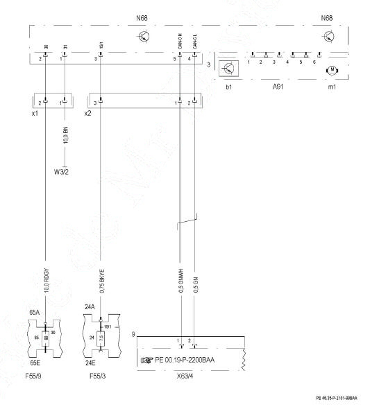
Power steering
Test yourself
A quick Mercedes-Benz B-Class quiz: every answer comes with an explanation and a link to the manual page.