Steering
Removal and installation of steering gear
In this manual: Steering
22steps
~132min
4/5difficulty
Done 0 of 22
REQUIRED TOOLS
- [1]. Subframe retaining bolt (ref. 169 589 00 62 00) (Fig.17).
REMOVAL
- Raise and support the front of the vehicle, then remove the front wheels.
- Remove the engine undertray.
Removal of the engine control unit from the steering gear
- Remove the air filter housing.
- Position the wheels straight ahead and lock the steering wheel in the centre position.
- Check the steering gear centre position: the marking on the steering column shaft must align with the marking on the steering gear (Fig.13).
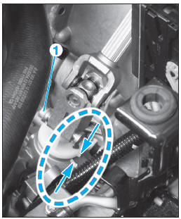
Fig. 13
- Remove screw (1), then disconnect the steering column shaft from the steering gear.
- Remove the bolts (arrows) from the heat shield (2), then set it aside (Fig.14).
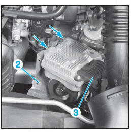
Fig. 14
- Disconnect the connectors from the steering control unit (3).
- Remove the bolts (4) from the steering motor control unit (5) (Fig.15).
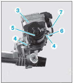
Fig. 15
 Pay attention to the installation position of the bracket (6) and the wiring harness (7).
- Remove the steering motor control unit (5) together with the steering control unit (3).
Cover the opening at the engine control unit on the steering gear and at the steering coupling with a lint-free cloth.- Remove the heat shield (2).
- Release the clip (8) (Fig.16).
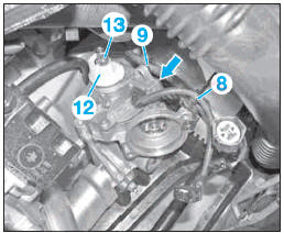
Fig. 16
- Cut the clip (9).
 If the clip (9) is removed incorrectly, the cover of the torque sensor board (arrow) may be damaged, which can allow moisture to enter and cause steering failure.
Lower the subframe
- Remove the throttle actuator (vehicles with particulate filter) or the intake air throttle (vehicles without particulate filter).
- Support the radiator.
- Move the rear of the wheel arches apart.
- Unhook the rubber exhaust mounts.
- Remove the earth strap bolt from the oil sump.
- On vehicles with manual transmission, unclip the clutch hydraulic line from the transmission and the underbody.
- With xenon headlights: disconnect the height sensor connector and remove its mountings.
- Place a support device under the subframe.
- Remove the 4 subframe mounting bolts (10) (Fig.17).
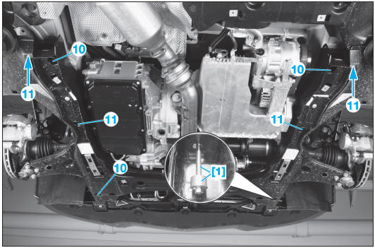
Fig. 17
- Instead of the subframe mounting bolts, install the retaining bolts with the stops [1].
Make sure the stops are centred on the retaining bolts.- Remove the 4 subframe mounting bolts (11).
- Lower the subframe.
Before lowering the subframe, make sure no wiring harness, hose or pipe will obstruct its descent.- Lift the engine/transmission assembly until the rubber mounts are unloaded.
- On vehicles with automatic transmission, remove the bolt (12) (Fig.18).
- Loosen the bolt (13).
- Remove the bolts (14), then the left engine mount (15).
- Disconnect the tie rod end from the steering knuckle.
- Loosen the stabilizer bar (16) from the subframe (17) (Fig.19).
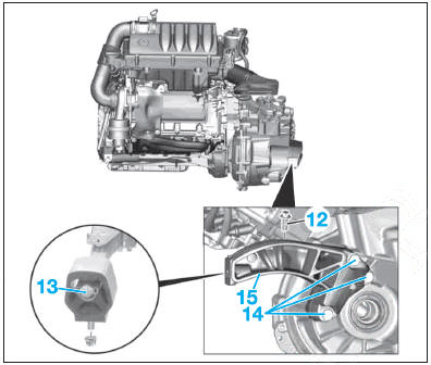
Fig. 18
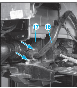
Fig. 19
- Remove (Fig.20):
- the mountings (18),
- the bolts (19),
- the heat shield (20).
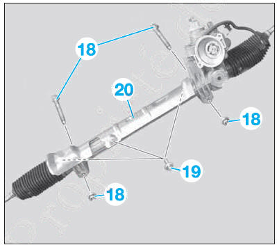
Fig. 20
- On vehicles with automatic transmission, remove the line (21) (Fig.21).
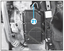
Fig. 21
- Lift the steering gear out of the subframe guides and remove it through the left wheel arch.
INSTALLATION
Refit in the reverse order of removal, observing the following points:
- on vehicles with automatic transmission, check the transmission fluid level and adjust it if necessary,
- if a new steering gear is installed, increase the tightening torque of the bolts (19) of the heat shield (20) by 1 daN.m compared with the specified torque,
- replace the mountings (18),
- on the steering motor control unit (5), check the seal (22) and its correct position, as well as the coupling (23) (Fig.22),
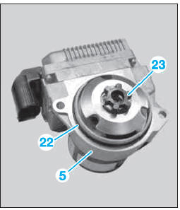
Fig. 22
- replace the bolt (1),
- check and adjust the toe alignment if necessary.
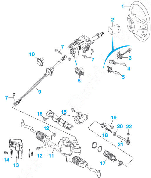
Steering column and rack
- Steering wheel
- Trim
- Clockspring
- Cruise control switch
- Turn signal, wiper and high beam switch
- Steering column tube
- Bolt (replace): 2 daN.m
- Steering column control unit
- Steering column shaft
- Boot
- Steering gear
- Steering gear mounting (replace):
- 1st pass: 4 daN.m.
- 2nd stage: 90°.
- Steering motor control unit and steering gear control unit
- Bolt: 2.3 daN.m
- Heat shield
- Bolts: 1 daN.m
- Boot
- Tie rod
- Bolt (replace): 8 daN.m
- Toe adjustment locknut: 6 daN.m
- Ball
- Bolt (replace): 6 daN.m.
Test yourself
A quick Mercedes-Benz B-Class quiz: every answer comes with an explanation and a link to the manual page.
Was this page helpful?