Headlamp Aiming Adjustment
Adjustment
PREPARATION BEFORE ADJUSTING
Before performing aiming adjustment, check the following.
Adjust the tire pressure to the specification.
Fill with fuel, coolant, and each oil.
Maintain the unloaded vehicle condition. (Remove luggage from the passenger compartment and the luggage room.)
Wipe out dirt on the headlamp.
Ride alone on the driver seat.
BULB CENTER WHEN ADJUSTING THE AIMING
When performing aiming adjustment, set headlamp (Lo) center at headlamp center mark  .

AIMING ADJUSTMENT SCREW
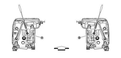
|
Headlamp LH (UP/DOWN) adjustment screw |
 |
Headlamp RH (UP/DOWN) adjustment screw |
||
| : vehicle front | |||||
| Adjustment screw | Screwdriver rotation | Facing direction | |
|---|---|---|---|
|
Headlamp LH (UP/DOWN) | Clockwise | UP |
| Counterclockwise | DOWN | ||
|
Headlamp RH (UP/DOWN) | Clockwise | UP |
| Counterclockwise | DOWN | ||
AIMING ADJUSTMENT PROCEDURE
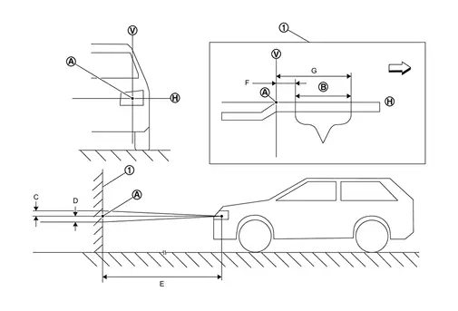
 |
Adjustment screen | ||||
|
Headlamp bulb center (H-V point) | |
Aim evaluation area |  |
Horizontal aiming evaluation line |
 |
Vertical aiming evaluation line | ||||
| C | Highest cutoff line height | D | Lowest cutoff line height | E | Distance of headlamp adjustment screen from headlamp |
| F | Minimum aim evaluation distance from vertical center on adjustment screen 133 mm (1°R) | G | Maximum aim evaluation distance from vertical center on adjustment screen 399 mm (3°R) | ||
| : vehicle right | |||||
| E | C | D | ||
|---|---|---|---|---|
| mm (in) | deg. | mm (in) | deg. | |
| 7.62 m (25 ft) | 23 mm (0.91 in) | 0.175° down | 43 mm (1.69 in) | 0.325° down |
| 10 m (32.8 ft) | 31 mm (1.22 in) | 0.175° down | 57 mm (2.24 in) | 0.325° down |
Use adjustment screw to perform aiming adjustment.
Ensure fog lamps are turned off (if equipped).
The vehicle should have its standard load, which may include any outfitting or other equipment. Any load that is normally carried in the vehicle should be in the vehicle while verifying or performing headlamp adjustment. Any other load should be removed.
Block the opposite headlamp from projecting a beam pattern onto the adjustment screen, using a suitable object. Aim each headlamp individually.
Place the screen on the same level and flat surface as the vehicle.
Face the front of the vehicle to the screen and measure distance between the headlamp and the screen surface.
| Distance between the headlamp center and the screen | : 7.62 m (25 ft) or 10 m (32.8 ft) |
Start the engine. Turn the headlamp on.
Determine the preferred vertical aim range dimensions, using the aiming chart.
Measure the projected beam within the aim evaluation segment on the screen.
Adjust the beam pattern of each headlamp until the aim evaluation segment (the area relative to both the highest and lowest cutoff line height) is positioned within the vertical aim range dimensions shown on the aiming chart.