Transaxle & transmissioN CVT: RE0F11A

Diagnosis and repair work flow

In this manual: Transaxle & transmissioN CVT: RE0F11A
Foreword — 1General information — 45Engine Mechanical MR16DDT — 61Engine Mechanical HR16DE — 52Engine Mechanical K9K — 46Engine Lubrication System MR16DDT — 18Engine Lubrication System HR16DE — 14Engine Lubrication System K9K — 11Engine Cooling System MR16DDT — 28Engine Cooling System HR16DE — 29Engine Cooling System K9K — 24Engine Control System MR16DDT — 163Engine Control System HR16DE — 115Engine Control System K9K — 129Fuel System MR16DDT — 13Fuel system HR16DE — 11Fuel system K9K — 12Exhaust system MR16DDT — 7Exhaust system HR16DE — 10Exhaust system K9K — 7Starting system — 24Accelerator control system — 6Clutch — 25Driveline transfer: TY21B — 77Driveline rear propeller Shaft: 3Fφ16-ETJ75 — 12Driveline rear final drive: RTVS — 31Transaxle & transmission 5MT: RS5F92R — 31Transaxle & transmission 6MT: RS6F94R — 30Transaxle & transmission CVT: RE0F10B — 93Transaxle & transmissioN CVT: RE0F11A — 103Front Axle MR16DDT — 18Front Axle HR16DE — 17Front Axle K9K — 17Rear Axle 2WD — 6Rear Axle 4WD — 13Front Suspension — 21Rear Suspension 2WD — 13Rear Suspension 4WD — 17Road Wheels & Tires — 6Brake System LHD — 24Brake System RHD — 24Parking Brake System — 8Brake Control System without ESP — 44Brake Control System with ESP — 63Steering System — 14Steering Control System — 27Seat Belt — 8SRS Airbag — 24SRS Airbag Control System — 93Ventilation System — 11Heater & Air Conditioning System HR16DE — 28Heater & Air Conditioning System MR16DDT — 28Heater & Air Conditioning Control System Type 1 — 49Heater & Air Conditioning Control System Type 2 — 51Heater & Air Conditioning Control System Type 3 — 32Heater & Air Conditioning Control System Type 4 — 40Heater & Air Conditioning Control System Type 5 — 21Interior — 16Instrument Panel — 10Seat — 18Door & Lock Type 1 — 83Door & Lock type 2 — 80Door & Lock type 3 — 65Door & Lock type 4 — 60Security Control System with intelligent key system — 82Security Control System without intelligent key system — 41Glass & Window System — 15Power Window Control System — 28Body Repair — 13Exterior — 20Mirrors — 26Exterior Lighting System Halogen type — 51Interior Lighting System — 24Wiper & Washer — 45Defogger — 31Horn — 4Power Outlet — 4Body Control System With intelligent key system — 21Body Control System Without intelligent key system — 23LAN system can fundamental — 6LAN system can — 31LAN System can system (type 1) — 1LAN System can system (type 2) — 1LAN System can system (type 3) — 1LAN System can system (type 4) — 1LAN System can system (type 5) — 1LAN System can system (type 6) — 1LAN System can system (type 7) — 2LAN System can system (type 8) — 1LAN System can system (type 9) — 1LAN System can system (type 10) — 1LAN System can system (type 11) — 1Power Control System IPDM E/R (with I-key) — 14Power Control System IPDM E/R (without I-key) — 14Power Control System Power distribution system — 25Charging System — 22Power Supply, Ground & Circuit Elements — 20Meter, Warning Lamp & Indicator — 33Warning Chime System — 22Audio, Visual & Navigation System Audio without navigation — 30Audio, Visual & Navigation System Audio with navigation — 33Audio, Visual & Navigation System NISSAN dynamic control system — 22Cruise Control System — 1Drive Mode System — 10Maintenance — 14
~3min read

Flowchart of Trouble Diagnosis

NOTE

:
“DTC” includes DTC at the 1st trip.

1.OBTAIN INFORMATION ABOUT SYMPTOM 1. Refer to TM-372, "Question sheet" and interview the customer to obtain the malfunction information (conditions and environment when the malfunction occurred) as much as possible when the customer brings in the vehicle.

2. Check the following:
- Service history
- Malfunction of harness and connector. GI-42, "Intermittent Incident".

>> GO TO 2.

2.CHECK DTC 1. Before checking the malfunction, check whether any DTC exists.

2. If DTC exists, perform the following operations.

- Records the DTCs. (Print out using CONSULT-III and affix to the Work Order Sheet.)
- Erase DTCs.

- Check the relation between the cause found by DTC and the malfunction information from customer. TM- 475, "Symptom Table" can be used effectively.

3. Check the relevant information including STI, etc.

Do malfunction information and DTC exist? Malfunction information and DTC exist.>>GO TO 3.

Malfunction information exists but no DTC.>>GO TO 4.

No malfunction information, but DTC exists.>>GO TO 5.

3.REPRODUCE MALFUCTION SYSTEM

Check the malfunction described by the customer on the vehicle.

Check if the behavior is fail safe or normal operation. Refer toTM-362, "Fail-Safe".

Interview sheet can be used effectively when reproduce malfunction conditions. Refer to TM-372, "Question sheet".

Verify the relationship between the symptom and the conditions in which the malfunction described by the customer occurs.

>> GO TO 5.

4.REPRODUCE MALFUNCTION SYMPTOM

Check the malfunction described by the customer on the vehicle.

Check if the behavior is fail safe or normal operation. Refer toTM-362, "Fail-Safe".

Interview sheet can be used effectively when reproduce malfunction conditions.TM-372, "Question sheet".

Verify the relationship between the symptom and the conditions in which the malfunction described by the customer occurs.

>> GO TO 6.

5.PERFORM “DTC CONFIRMATION PROCEDURE”

Perform “DTC CONFIRMATION PROCEDURE” of the appropriate DTC to check if DTC is detected again.

Refer to TM-365, "DTC Inspection Priority Chart" when multiple DTCs are detected, and then determine the order for performing the diagnosis.

Is any DTC detected? YES >> GO TO 7.

NO >> Follow GI-42, "Intermittent Incident" to chec

6.IDENTIFY MALFUNCTIONING SYSTEM WITH “DIAGNOSIS CHART BY SYMPTOM”

Use TM-475, "Symptom Table" from the symptom inspection result in step 4. Then identify where to start performing the diagnosis based on possible causes and symptoms.

>> GO TO 8.

7.REPAIR OR REPLACE THE MALFUNCTIONING PARTS

Repair or replace the detected malfunctioning parts.

Reconnect parts or connector after repairing or replacing, and then erase DTC if necessary.

>> GO TO 8.

8.FINAL CHECK

Perform “DTC CONFIRMATION PROCEDURE” again to make sure that the repair is correctly performed.

Check that malfunctions are not reproduced when obtaining the malfunction information from the customer, referring to the symptom inspection result in step 3 or 4.

Is DTC or malfunction symptom reproduced? YES-1 (DTC is reproduced.)>>GO TO 5.

YES-2 (Malfunction is reproduced.)>>GO TO 6.

NO >> Before delivering the vehicle to the customer, make sure that DTC is erased.

Question sheet

DESCRIPTION

There are many operating conditions that may cause a malfunction of the transmission parts. By understanding those conditions properly, a quick and exact diagnosis can be achieved.

In general, perception of a problem varies depending on individuals.

Ask the customer about his/her concerns carefully. It is important to understand the phenomenon or status. To systemize all the information for the diagnosis, prepare the question sheet referring to the question points.

In some cases, multiple conditions that appear simultaneously may cause a DTC to be detected.

Worksheet Sample
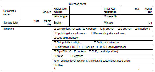
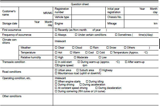
Worksheet Sample


Additional service when replacing TCM