All Wheel Drive
Removal
Remove battery tray. Refer to Removal and Installation.
Remove the cowl top cover and the cowl top extension. Refer to Removal and Installation - Cowl Top Extension.
Remove engine room cover. Refer to Removal and Installation.
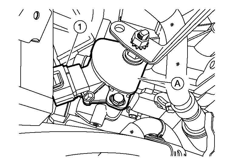
Disconnect the harness connector (A) from the transmission range switch (1).
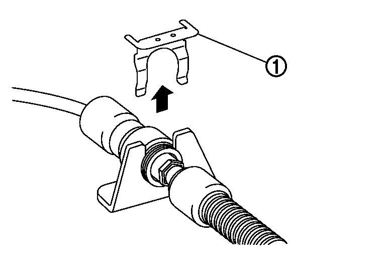
Remove lock plate (1) as shown.
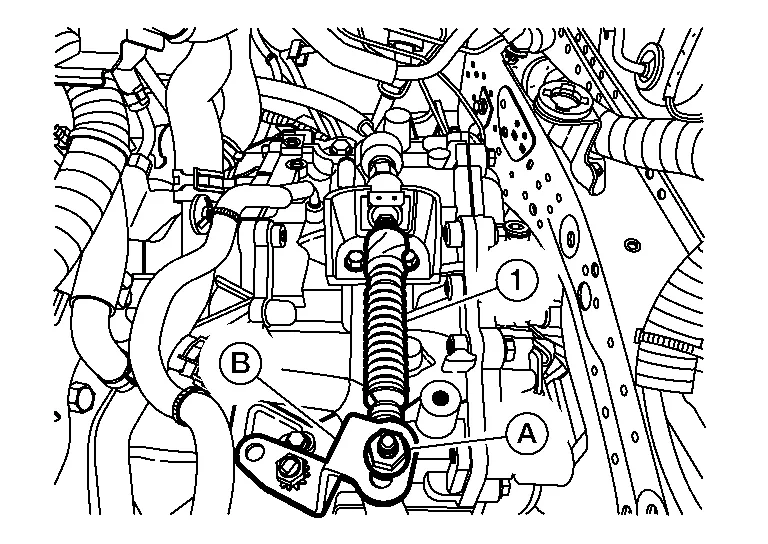
Remove nut (A) and separate control cable (1) from the manual lever (B).
Disconnect brake booster vacuum hose from intake manifold collector. Refer to Exploded View.
Disconnect PCV hose from intake manifold collector.
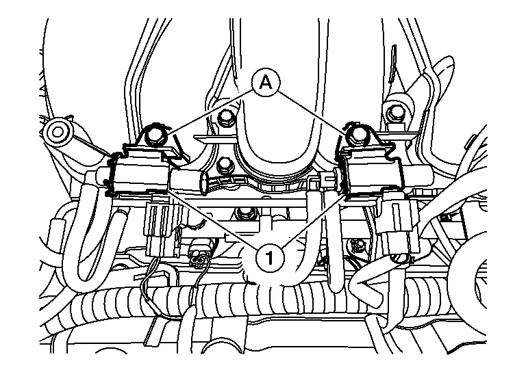
Remove bolts (A) and set VIAS control solenoid valves (1) aside.
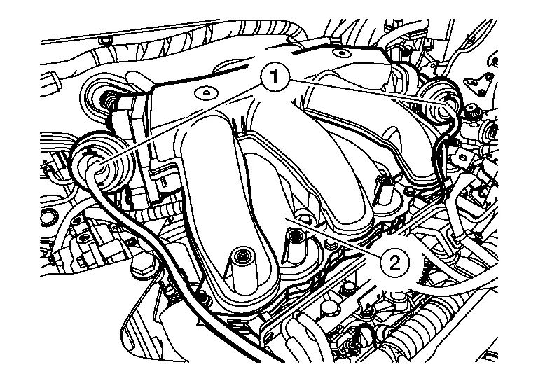
Disconnect vacuum hoses (1) from intake manifold collector (2).
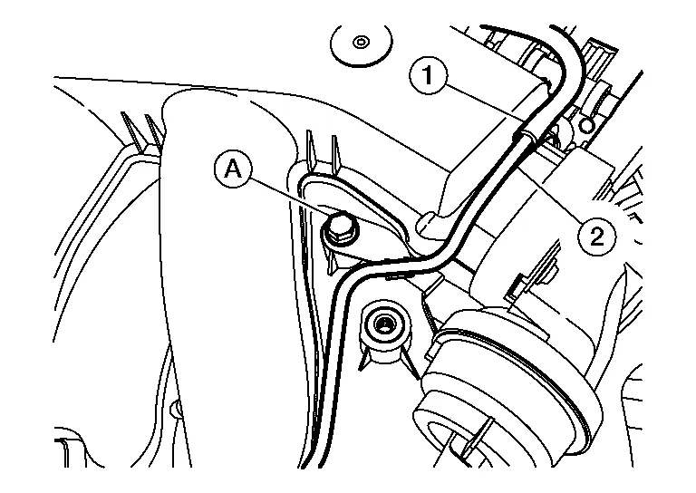
Disconnect vacuum hose (1) from vacuum pipe (2).
Remove bolt (A).
Remove clamp (1) and disconnect hose (2) from pipe (3).
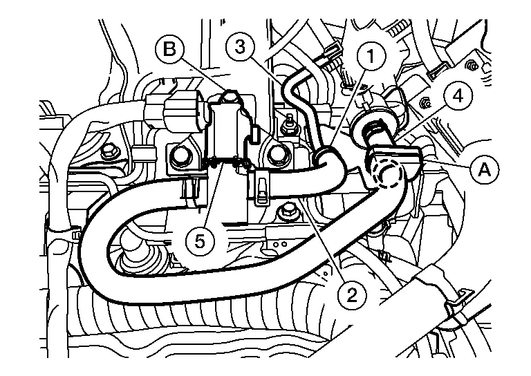
Using suitable tool, release pawl and remove hose (4) from retainer (A).
 |
: Pawl |
Remove bolt (B) and set EVAP canister purge volume control solenoid (5) aside.
Set vacuum tube assembly (1) aside.
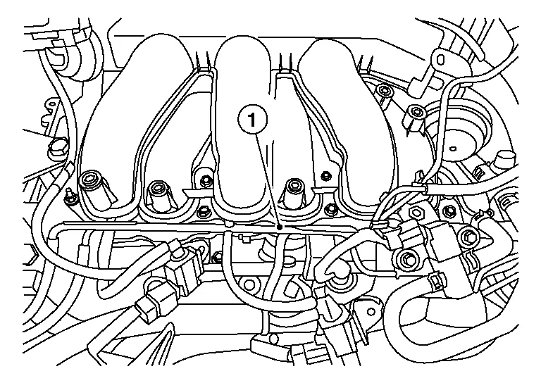
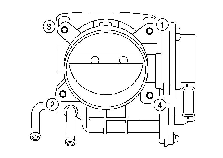
Loosen bolts in reverse of sequence shown and remove electric throttle control actuator bolts, then remove electric throttle control actuator and position aside.
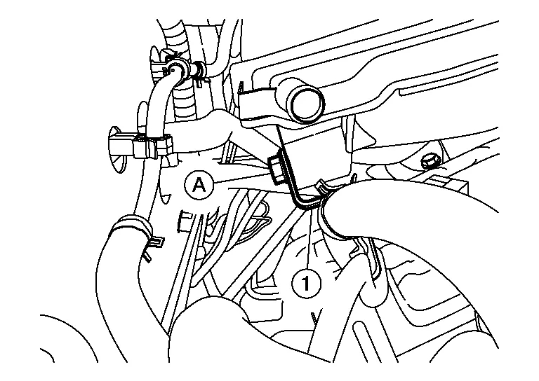
Remove bolt (A) and set bracket (1) aside.
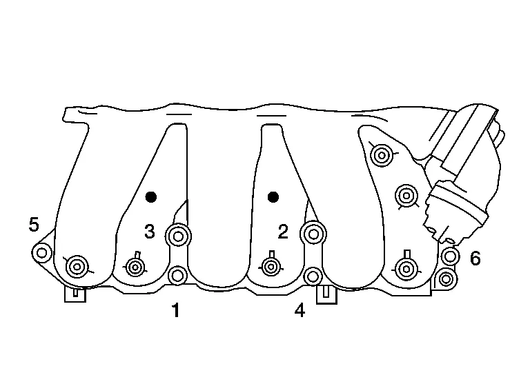
Loosen the intake manifold collector bolts and nuts in reverse of the sequence shown, then remove the intake manifold collector and gasket.
Disconnect transaxle breather hose (1) from transaxle assembly.

Remove bolt (A) from CVT charge pipe (1).
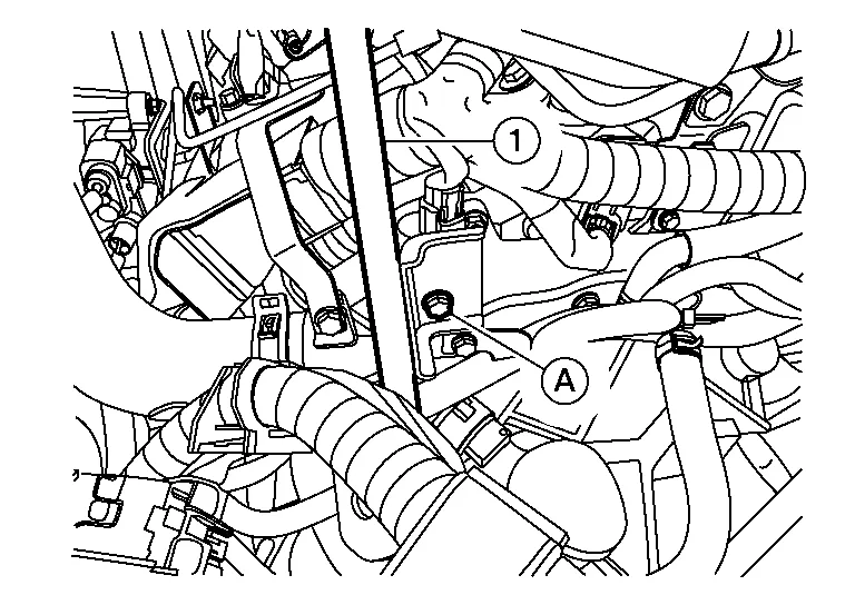
Remove bolt (A) from upper torque rod.
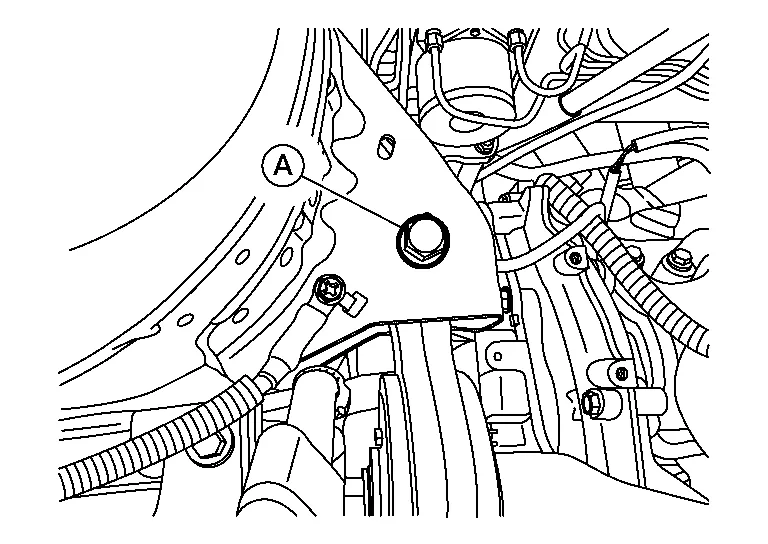
Disconnect air fuel ratio sensor 1 (bank 1) and remove exhaust manifold cover (bank 1). Refer to Exploded View.
Remove top nuts from three way catalyst (bank 1). Refer to Exploded View.
Remove fuel tube bolts (A).

Remove CVT gusset bolt (A).
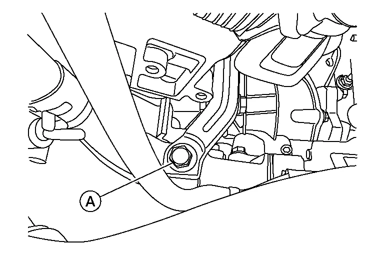
Remove bolts (A).
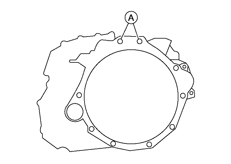
Remove nuts (A) and bracket (1).

Using a suitable tool, release clip.

 |
: Clip |
Install Tool (B) using bolts (A) and (C) supplied with Tool. Tighten bolts to specification. Refer to Engine Support Tool Operating Instructions.
| Tool (B) | : (J-52604) |
| Bolts (A) | : 20 N·m |
| Bolts (C) | : 11 N·m |
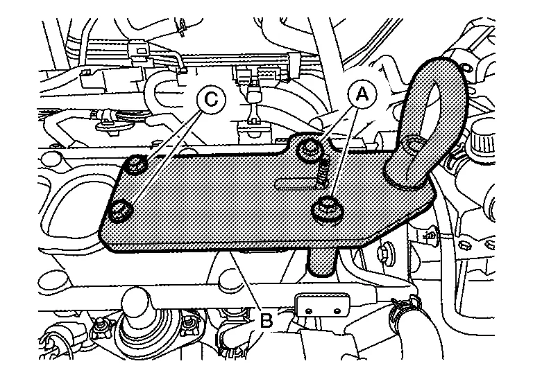
Install Tool (A) to drivers side frame rail (1) as shown. Refer to Engine Support Tool Operating Instructions.
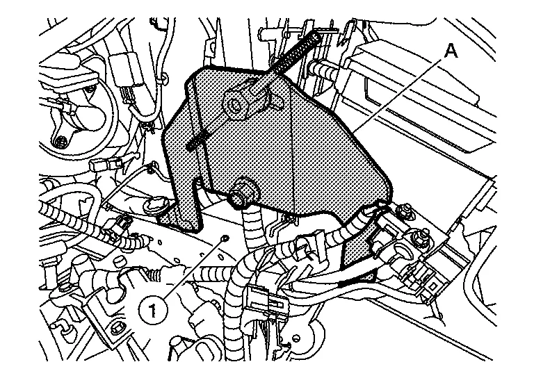
| Tool (A) | : (J-52389) |
Install Tool (A) on top of engine mounting insulator [RH (1)] as shown. Refer to Engine Support Tool Operating Instructions.

| Tool (A) | : (J-52389) |
Install Tool (A) to Tool (B). Refer to Engine Support Tool Operating Instructions.
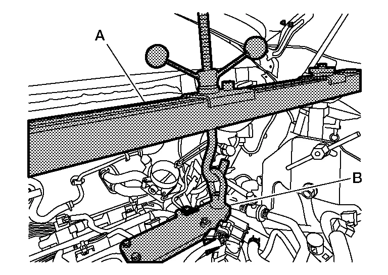
| Tool (A) | : (J-52389) |
| Tool (B) | : (J-52604) |
Using bubble level (B) on Tool (A) level Tool as shown. Refer to Engine Support Tool Operating Instructions.
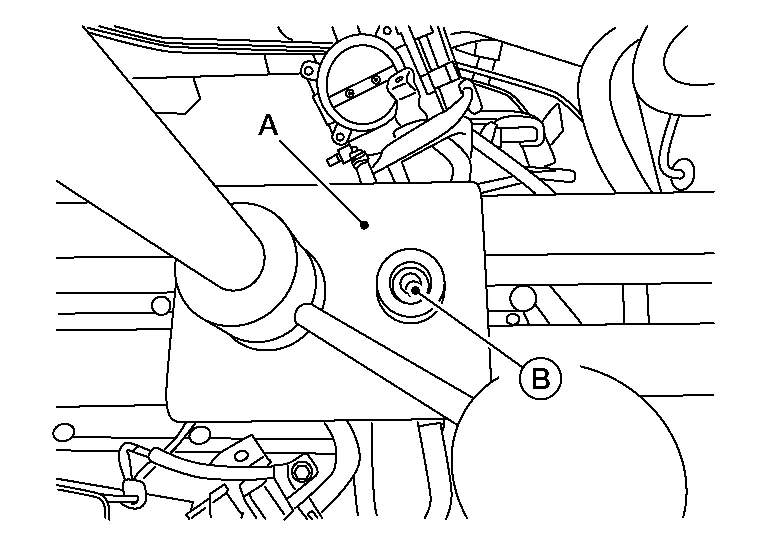
| Tool (A) | : (J-52389) |
Remove nut from engine mounting insulator (rear). Refer to Exploded View.
Remove front under cover. Refer to Removal and Installation.
Remove the front wheels and tires using power tool (LH/RH).
Remove the lock plates [A (LH/RH)] and remove brake hoses from struts.
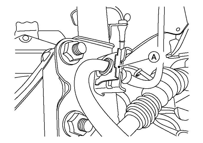
Remove nuts and separate stabilizer connecting rods from struts (LH/RH). Refer to Exploded View.
Remove the brake caliper torque member bolts, leaving brake hoses attached. Position the brake calipers aside with wire (LH/RH). Refer to Exploded View.
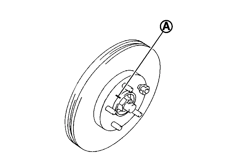
Put alignment (A) marks on disc brake rotors and on the wheel hub and bearings. Remove the disc brake rotors (LH/RH).
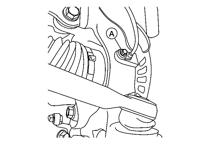
Remove wheel sensor bolts (A) and position wheel sensors aside (LH/RH).
Remove cotter pins from front drive shafts (LH/RH).
Remove the nut retainers from front drive shafts (LH/RH).
Loosen the wheel hub lock nuts from the drive shafts using power tool (LH/RH).
Using a piece of wood and a suitable tool, tap on the wheel hub lock nuts to disengage the drive shafts from the wheel hub and bearings (LH/RH).
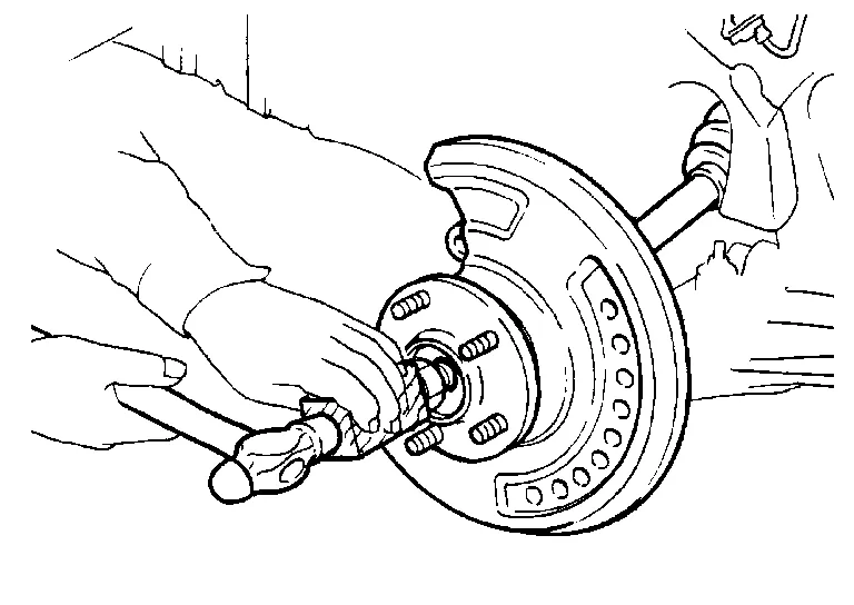
Remove the wheel hub lock nuts (LH/RH).
Remove the lower strut bolts and nuts. Separate the steering knuckles from the struts (LH/RH). Refer to Exploded View.
Remove bearing retainer to support bearing bracket bolts (RH only).
Insert suitable tool (A) between the drive shafts and transaxle. Remove the drive shafts from the transaxle (LH/RH).
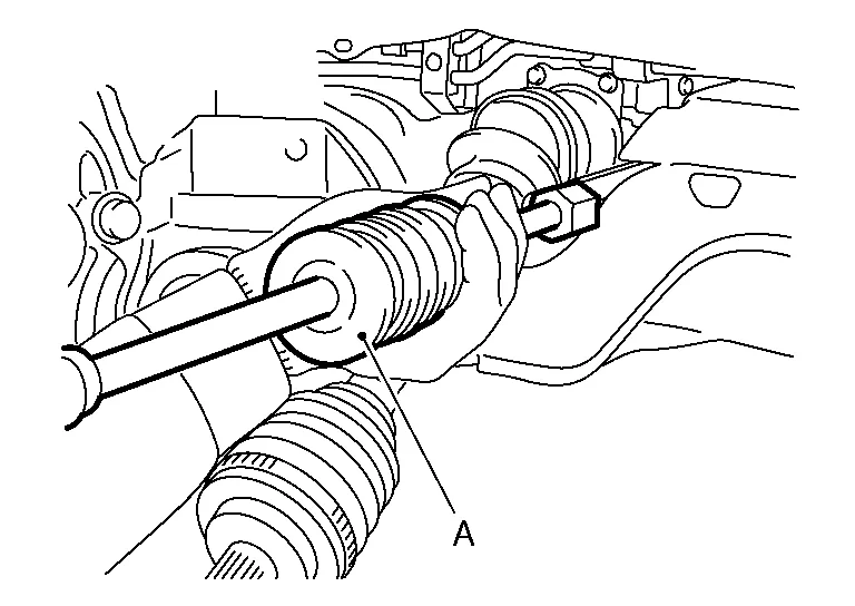
| Tool (A) | Drive shaft joint puller (Commercially available) |
Remove the differential side oil seals (LH/RH).
Remove nut and separate stabilizer connecting rods from struts (LH/RH). Refer to Exploded View.
Remove outer socket cotter pins (LH/RH). Refer to Exploded View.
Loosen the outer socket nuts and separate outer sockets from the steering knuckles (LH/RH) using ball joint remover (commercially available).
Remove the outer socket nuts and separate the outer sockets from the steering knuckles (LH/RH).
Remove front fender protector side covers (LH/RH). Refer to Exploded View.
Remove front fender protectors (LH/RH). Refer to Exploded View.
Remove bolt (A) and position crankshaft position sensor (1) aside.

Remove the front exhaust tube. Refer to Exploded View.
Disconnect the front engine mount insulator vacuum hose (1).
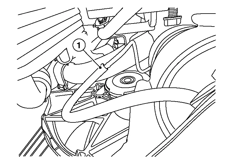
Remove bolt (A) from engine mounting insulator (front) pipe bracket.

Remove engine mounting insulator (front). Refer to Exploded View.
Remove bolt (A) and set bracket (1) aside.
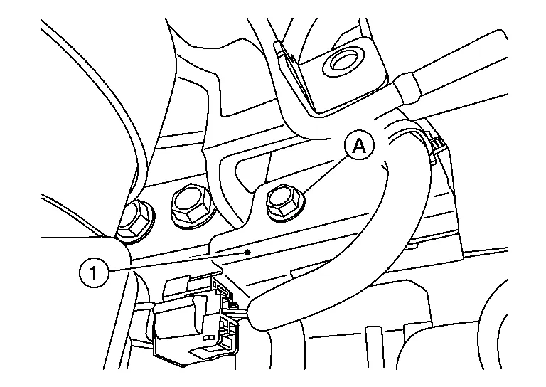
Remove bolt (A) and remove rear plate cover (1).
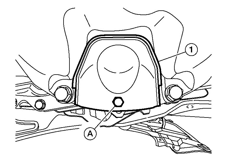
Hold drive plate with a suitable tool and remove torque converter nuts. Refer to Exploded View.
Drain power steering fluid. Refer to Draining and Refilling.
Using a suitable tool, release clip.
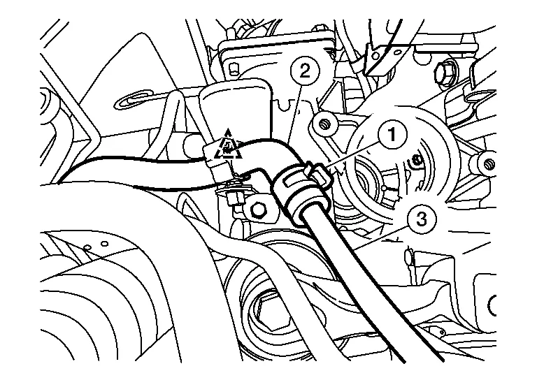
|
: Clip |
Release hose clamp (1) and separate the high pressure piping [lower (2)] from the low pressure piping [upper (3)].
Remove the power steering tube bracket bolts. Refer to Exploded View.
Using a suitable tool, release the retainer (A).
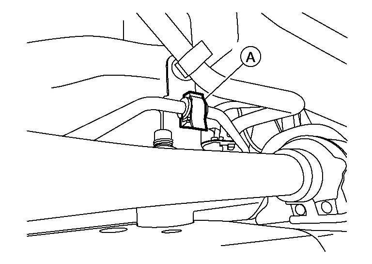
Separate the high pressure piping (A) from the steering gear (1).
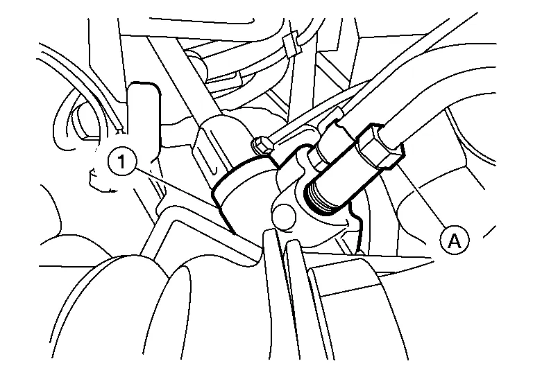
Remove lower bolt and separate the steering intermediate shaft from the steering gear.
Remove bolts (A) and (B) and remove rear propeller shaft heat shield (1).

Remove bolts and disconnect rear propeller shaft from transfer assembly. Refer to Exploded View.
Using suitable wire, secure the rear propeller shaft.
Remove bolts (A) from transaxle mount.
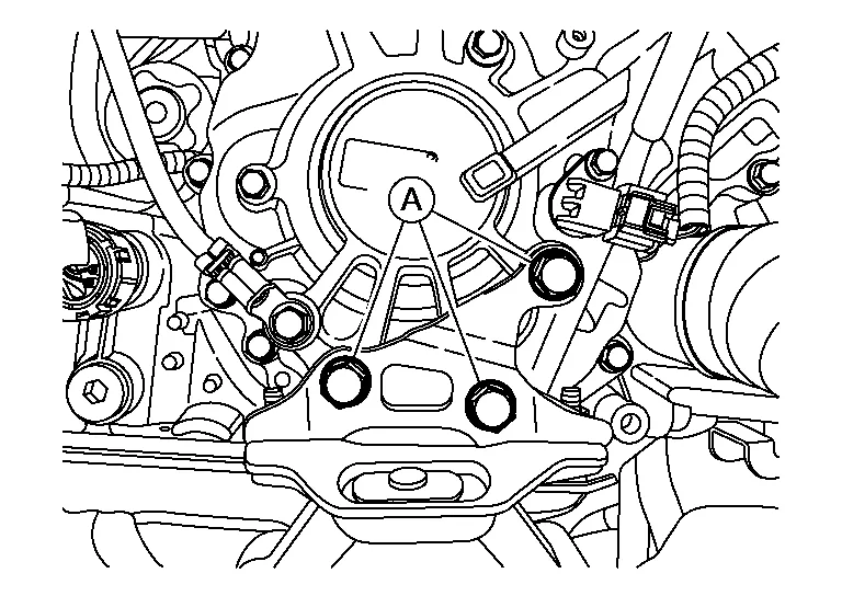
Remove bolt (A) and position ground (1) aside.
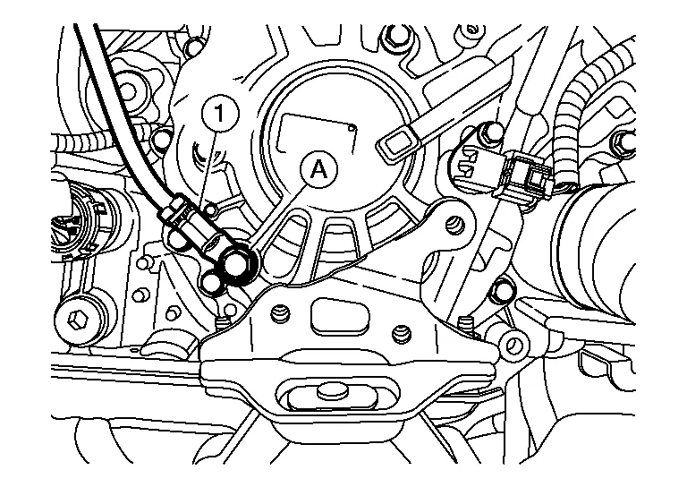
Remove water hose (1) from retainer (A).
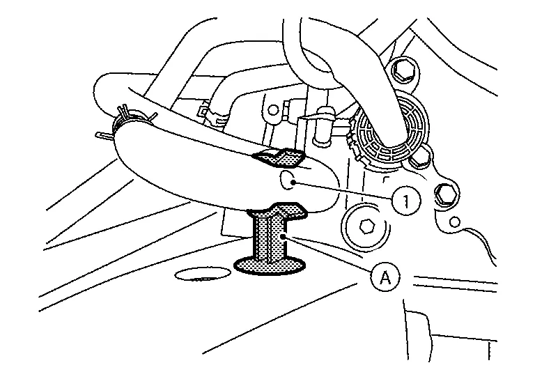
Remove rear torque rod bolt. Refer to Exploded View.
Set hydraulic lift table (A) or equivalent tool under front suspension member.
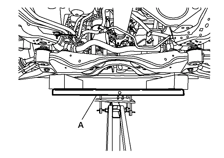
Remove front suspension member bolts and front suspension member stays. Refer to Exploded View.
Lower the front suspension member.
Remove bolt from heater thermostat bracket. Refer to Exploded View.
Drain engine coolant. Refer to Changing Engine Coolant.
Remove CVT fluid cooler hose A and CVT fluid cooler hose D from the CVT oil warmer. Refer to Exploded View.
Remove CVT water hose A and CVT water hose B from CVT oil warmer. Refer to Exploded View.
Disconnect the harness connector (A) from heated oxygen sensor 2 (bank 2).
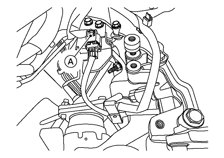
Separate the harness (1) from the bracket (2).

Remove bottom bolts from three way catalyst (bank 1). Refer to Exploded View.
Remove bolts (A) and remove engine mount bracket [rear (1)].

Remove rear gusset and transfer gusset. Refer to Exploded View.
Remove bolts (A), (B) and (C).
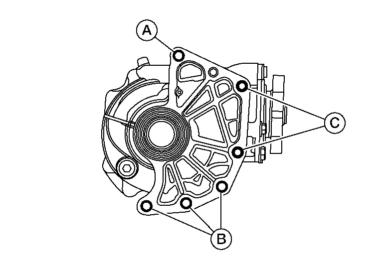
Remove transfer assembly from the Nissan Murano vehicle.
Using Tools lower engine and transaxle assembly until the transaxle assembly is low enough to clear driver’s side frame rail.
| Tool numbers | : (J-52389, J-52604) |
Disconnect the harness connector from the starter motor "S" terminal. Refer to Exploded View.
Remove nut and remove "B" terminal harness and position aside. Refer to Exploded View.
Remove starter motor bolts and remove starter motor. Refer to Exploded View.
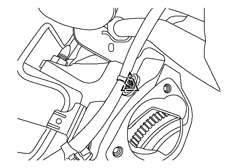
Using a suitable tool, release the clip.
|
: Clip |
Remove bolt (A) and remove CVT fluid charging pipe (1).
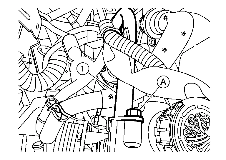
Separate the harness retainers from the transaxle assembly.
Disconnect the harness connector (A) from the transaxle assembly.

Disconnect the harness connector from the output speed sensor. Refer to Exploded View.
Disconnect the harness connector from the primary speed sensor. Refer to Exploded View.
Disconnect the harness connector from the input speed sensor. Refer to Exploded View.
Support transaxle assembly using a suitable transmission jack and Tool.
| Tool number | : (J-51307) |
Remove bolts (A), (B), (C), and (D).

Separate the transaxle assembly from the engine assembly and lower transaxle assembly.
INSTALLATION
Installation is in the reverse order of removal.
If replacing CVT, flush the CVT fluid cooler and lines. Refer to CVT Fluid Cooler Flush.
Perform inspection before installation. Refer to "Inspection Before Installation" below.
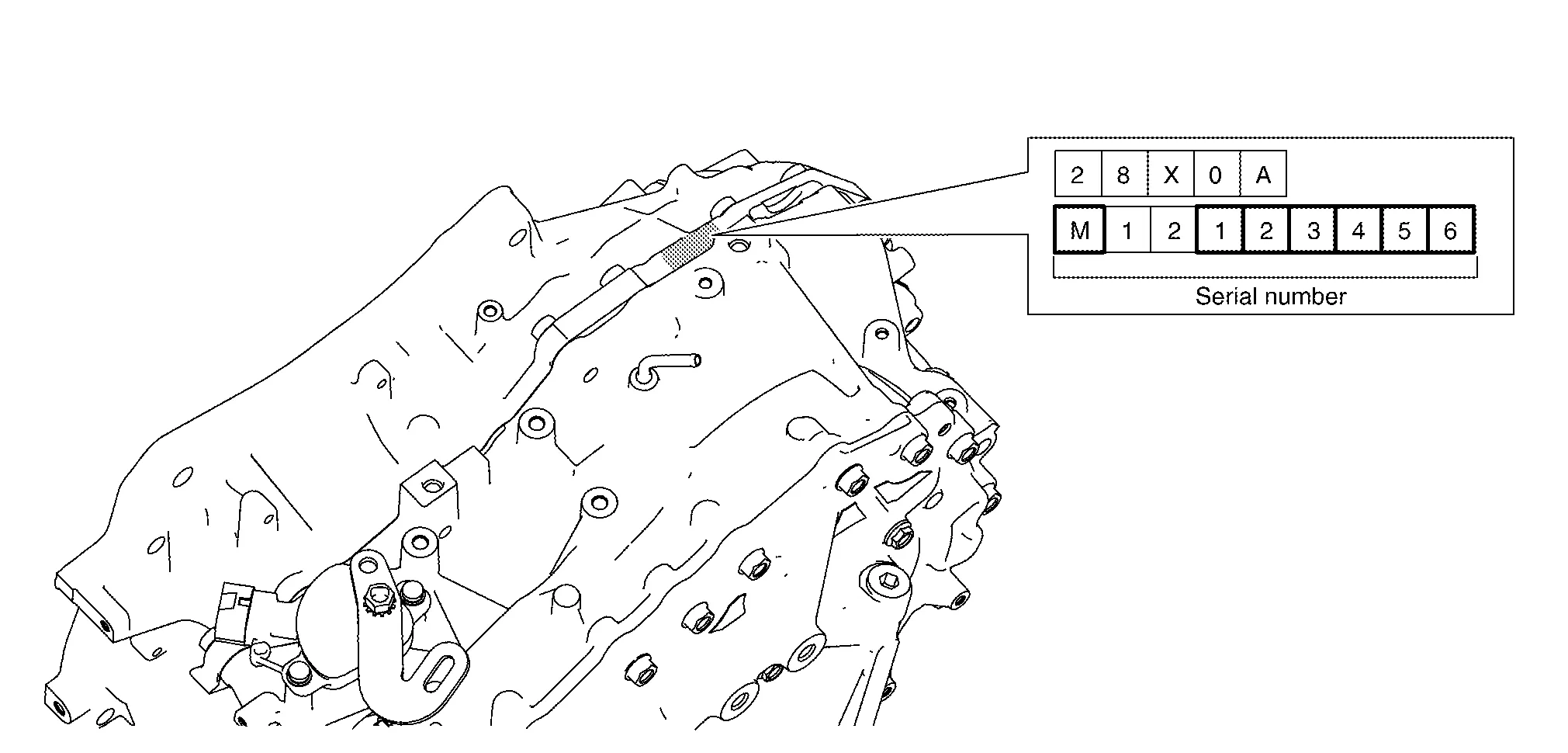
INSPECTION BEFORE INSTALLATION
After inserting a torque converter to the CVT, check dimension (A) with in the reference value limit.

| B | : Scale |
| C | : Straightedge Torque Converter |
| Dimension (A) | : Refer to Torque Converter. |
Adjustment After Installation
Perform the following:
Adjust CVT position. Refer to Adjustment.
Check and adjust the engine coolant level. Refer to Changing Engine Coolant.
Adjust the CVT fluid level. Refer to Adjustment.
Perform accelerator pedal released position learning. Refer to Description.
Perform throttle valve closed position learning. Refer to Description.
Perform front wheel alignment. Refer to Adjustment.
Perform adjustment of steering angle sensor neutral position. Refer to Description.
INSPECTION AFTER INSTALLATION
Check the following items:
CVT fluid leakage, refer to Inspection.
For CVT shifter position, refer to Inspection and Adjustment.
Start the engine and check for coolant leaks.