Unit Removal and Installation. Transfer Assembly
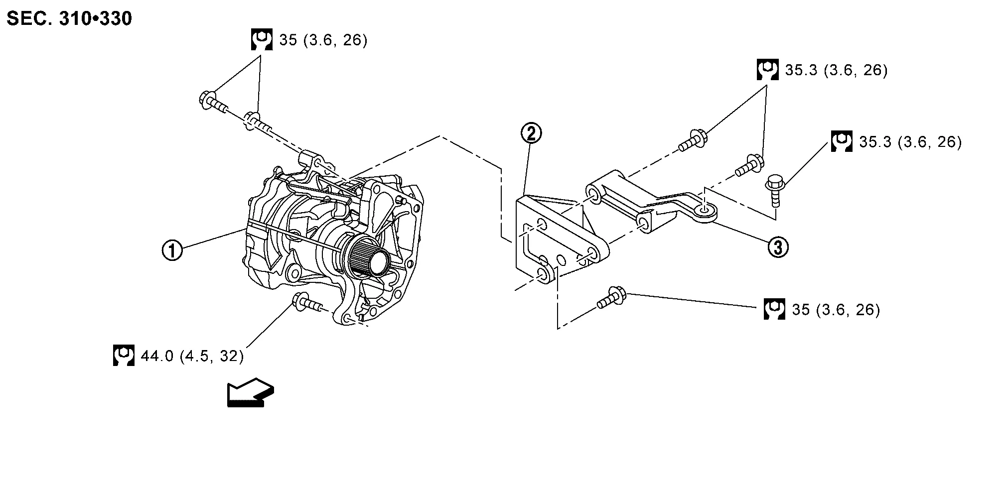
 |
Transfer assembly |  |
Transfer gusset |  |
Rear gusset |
 : Nissan Murano Vehicle front |
|||||
 : N·m (kg-m, ft-lb) |
|||||
REMOVAL
Drain the transfer oil. Refer to Draining.
Remove the cowl top and the lower cowl top extension. Refer to Exploded View.
Release clamp and separate reservoir tank hose from reservoir tank. Refer to Exploded View.
Remove reservoir tank. Refer to Exploded View.
Remove engine mounting bracket (front). Refer to Exploded View.
Remove the front wheel and tire (RH) using power tool. Refer to Removal and Installation.
Remove the front under cover. Refer to Removal and Installation.
Remove the fender protector side cover (RH). Refer to Removal and Installation.
Remove engine mounting insulator (front). Refer to Exploded View.
Remove the front exhaust tube, hanger and heat insulator. Refer to Exploded View.
Remove the propeller shaft from the transfer assembly and position aside. Refer to Removal and Installation
Remove the cotter pin.
Remove the nut retainer.
loosen the wheel hub lock nut from the drive shaft using a power tool.
Using a piece of wood and a suitable tool, tap on the wheel hub lock nut to disengage the drive shaft from the wheel hub and bearing.
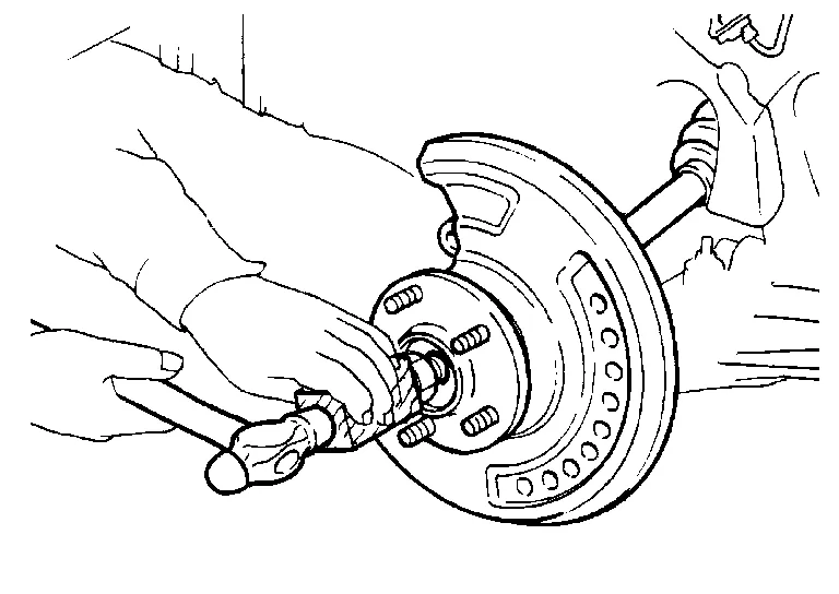
Remove the wheel hub lock nut.
Remove the lower strut bolts and nuts.
Separate the front strut from the steering knuckle. Refer to Exploded View.
Remove the bearing retainer to support bearing bracket bolts.
Remove the bearing retainer.
Insert suitable tool (A) between the drive shaft and the transfer assembly. Remove the drive shaft.
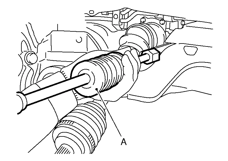
| Tool (A) | : Drive shaft joint puller (Commercially available) |
Remove exhaust manifold and three way catalyst heat shields with power tool.
Remove the three way catalyst support bolt (bank 1). Refer to Exploded View.
Disconnect the harness connector from each sensor, and remove the harness from the bracket and middle clamp. Refer to Exploded View.
Remove the three way catalyst (bank 1) by loosening the bolts first and then removing the nuts and through bolts.
Loosen the exhaust manifold nuts in reverse of the order shown.
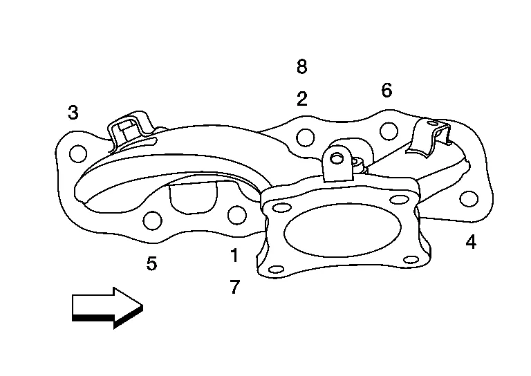
|
: Engine front |
Remove the exhaust manifold (bank 1).
Support transaxle with a suitable jack.
Remove engine mounting insulator (LH). Refer to Exploded View.
Remove rear gusset and transfer gusset.
Remove transaxle assembly to transfer assembly bolts.
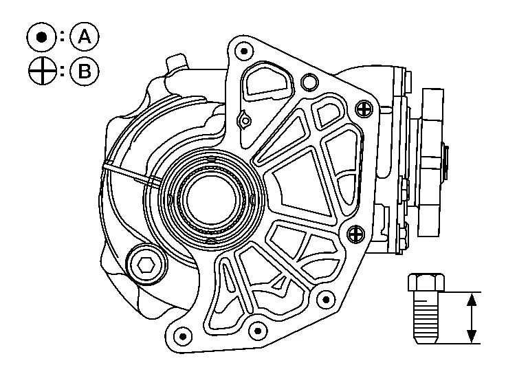
| Bolt No. | (A) | (B) |
|---|---|---|
| Quantity | 4 | 2 |
Bolt length “ ” mm (in) |
44 (1.73) | 42 (1.65) |
Remove transfer assembly from the Nissan Murano vehicle.
Remove the drive shaft oil seal using the following procedure:Using a suitable tool, remove the transfer cover oil seal.
Remove the drive shaft oil seal (1) using suitable tool (A).
INSTALLATION
Installation is in the reverse order of removal.
When installing the transfer to the transaxle, install the bolts following the standard below.
Bolt No. (A) (B) Quantity 4 2 Bolt length “ ” mm (in)44 (1.73) 42 (1.65) Do not reuse differential side oil seal.
Check transfer oil level and check for transfer oil leaks after installation. Refer to Refilling.
Install the drive shaft oil seal and transfer cover oil seal using the following procedure:Install drive shaft oil seal (1) onto Tool (A) before installing into transfer case assembly using Tool (B).
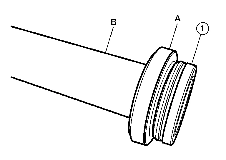
| Tool (A) | : — (J-52390) |
| Tool (B) | : — (J-8092) |
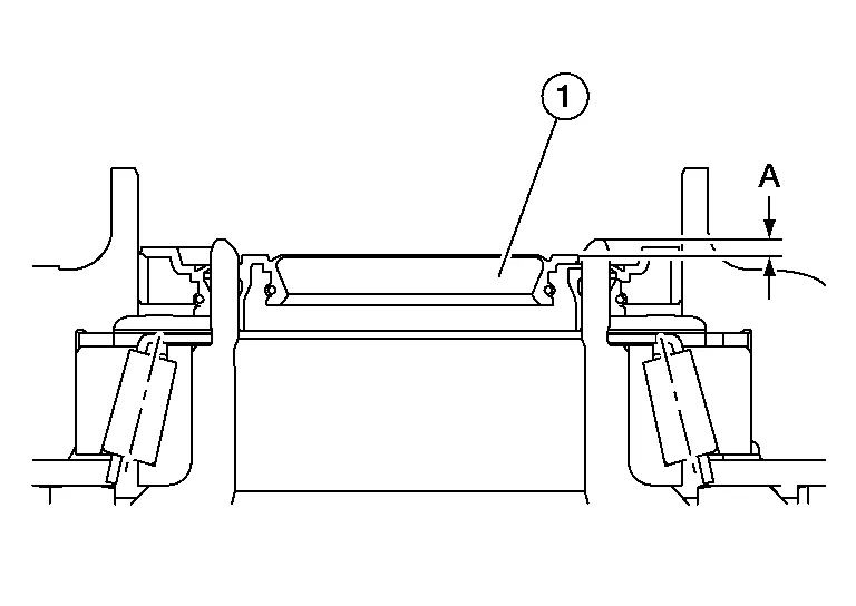
| Dimension (A) | : 2.0 - 2.6 mm (0.079 - 0.102 in) |

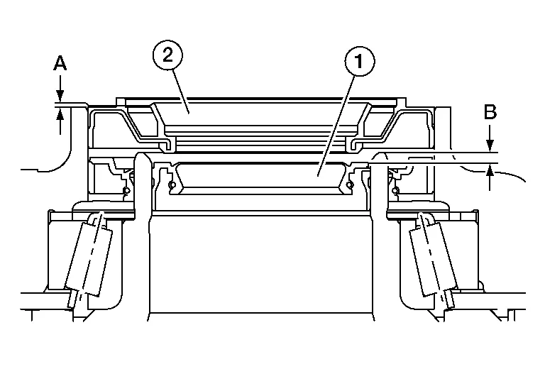
| Dimension (A) | : 0.0 - 0.6 mm (0.000 - 0.024 in) |
| (1) | : Drive shaft oil seal |
| (B) | : Drive shaft oil seal installation depth |
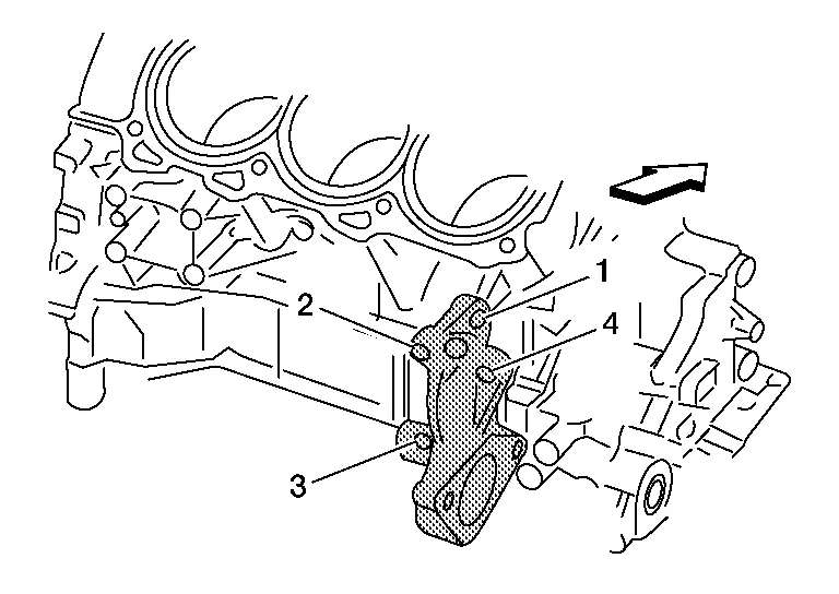
Install the support bearing bracket.
Tighten the support bearing bracket bolts in numerical order as shown.
Refer to the following for installation positions of the bolts:
| M10 bolt | No. 1 - 4: | 48 N·m |
|
: Front |
In order to prevent damage to the transfer cover oil seal, place Tool (A) onto the applicable oil seal before inserting the drive shaft as shown. Slide the drive shaft into the slide joint and tap with a hammer to install securely.
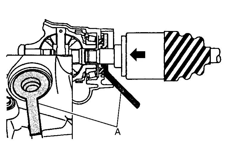
| Tool (A) | : KV38107900 (J-52469–1) |
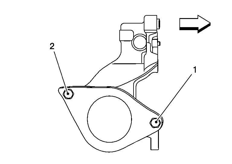
Install the bearing retainer.
Tighten the bearing retainer bolts in the numerical order shown.
| M8 bolt | No. 1 and No. 2: | 25 N·m |
|
: Front |
Pull the joint sub-assembly in the axial direction away from the transfer assembly. Confirm the joint sub-assembly cannot be pulled out.
Clean the matching surfaces of the wheel hub lock nut and the wheel hub and bearing.
Tighten the wheel hub lock nut to specification. Refer to Exploded View (RH).
When installing the cotter pin (1) and the nut retainer (2), securely bend the cotter pin to prevent rattles.

Install the studs in the exhaust manifold (if removed), and tighten to specification.
| Exhaust manifold studs | : 15,4 N·m |
Install the exhaust manifold gasket in the direction shown.
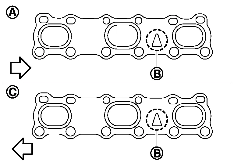
| (A) | : Bank 1 |
| (B) | : Triangle press |
| (C) | : Bank 2 |
|
: Engine front |
Install the exhaust manifold (bank 1) nuts and tighten to specification in the order shown.
|
: Engine front |
Installation of remaining components is in the reverse order of removal.