Water Pump
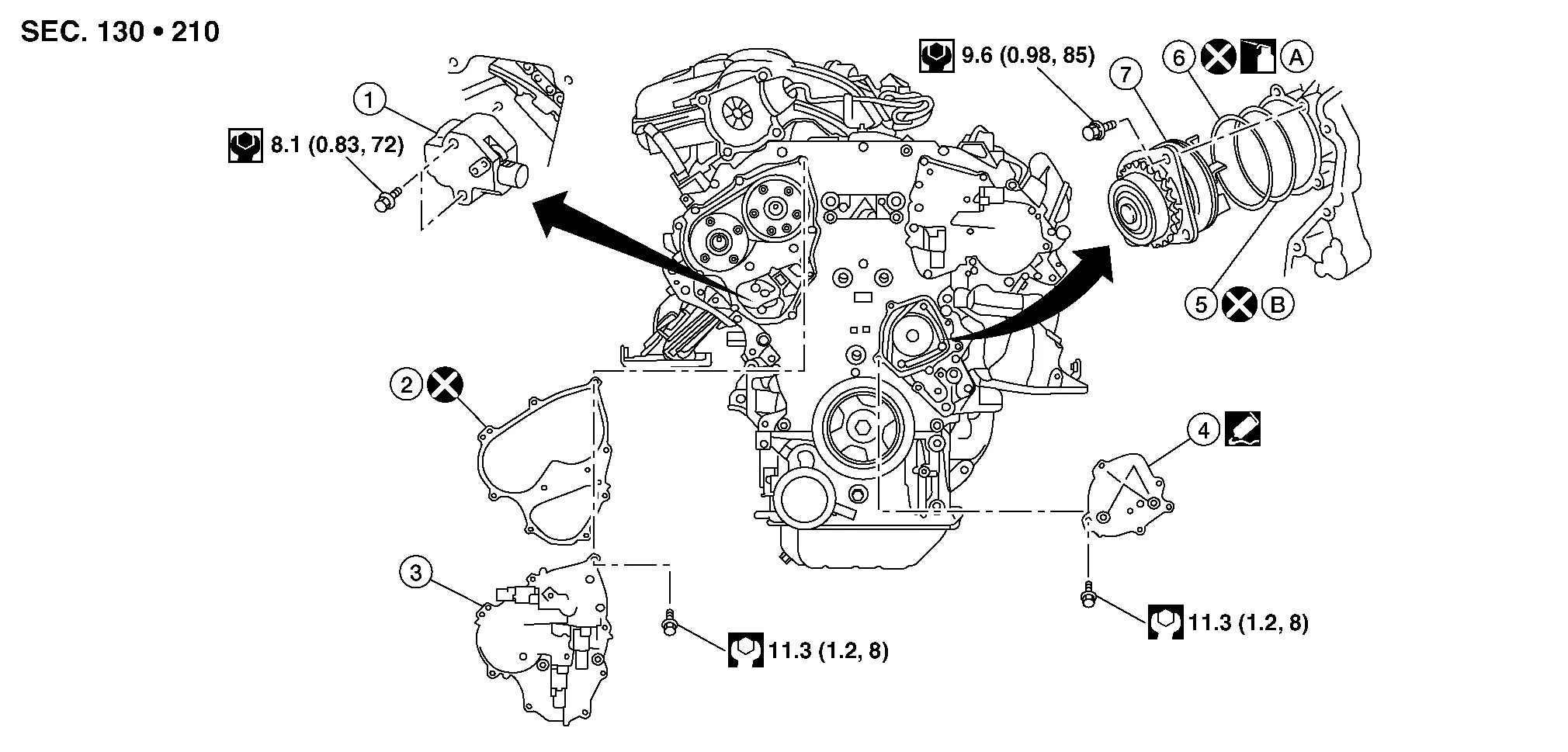
| 1. | Timing chain tensioner (primary) | 2. | Valve timing control cover gasket (bank 1) | 3. | Valve timing control cover (bank 1) |
| 4. | Water pump cover | 5. | O-ring | 6. | O-ring (Identify with white mark) |
| 7. | Water pump | A. | Apply engine oil | B. | Apply engine coolant |
REMOVAL
Disconnect the negative battery terminal. Refer to Removal and Installation.
Remove the engine room cover. Refer to Removal and Installation.
Remove front under cover. Refer to Removal and Installation.
Drain engine coolant from the radiator. Refer to Changing Engine Coolant.
Drain power steering fluid. Refer to Draining and Refilling.
Remove the cowl top cover and the cowl top extension. Refer to Exploded View.
Remove sub tank bracket from cowl top extension.
Remove brake fluid level sensor harness connector from brake fluid level sensor.
Remove strut tower brace.
Remove front air duct. Refer to Removal and Installation.
Remove the front road wheel and tire (RH) using a power tool. Refer to Removal and Installation.
Remove the fender protector (RH). Refer to Removal and Installation.
Disconnect engine coolant reservoir hose and remove engine coolant reservoir tank.
Set No. 1 cylinder at TDC on its compression stroke.
Align pointer with TDC mark on crankshaft pulley.
Remove drive belt. Refer to Removal and Installation.
Remove the drive belt auto-tensioner assembly. Refer to Removal and Installation of Drive Belt Auto-Tensioner.
Drain engine coolant from cylinder block (if necessary). Refer to Changing Engine Coolant.
Remove the E-PSF cover, bracket and motor. Refer to Removal and Installation.
Support engine and remove the RH engine insulator and bracket. Refer to Exploded View.
Disconnect the A/C lines at the junction. Refer to Exploded View.
Disconnect RH valve timing control connectors and remove valve timing control cover (bank 1). Refer to Exploded View.
Remove water pump cover. Refer to Exploded View.
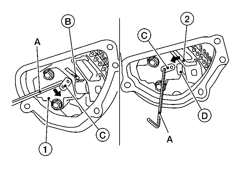
Remove the timing chain tensioner (primary) as follows:Pull the lever (C) down to release the plunger stopper tab (B).
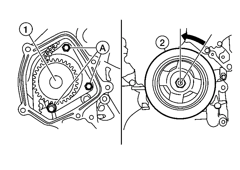
Remove the three water pump bolts (A). Make a gap between water pump sprocket (1) and timing chain by carefully turning crankshaft pulley (2) counterclockwise until timing chain loosens on water pump sprocket (1).
Screw M8 bolts [pitch: 1.25 mm (0.49 in) length: approx. 50 mm (1.97in)] into water pumps upper and lower bolt holes until they reach the timing chain case.

Hold the timing chain to the side using a suitable tool and alternately tighten the M8 bolts for a half turn until the water pump can be removed.
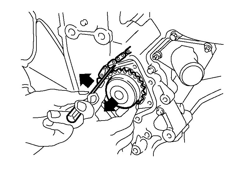
Remove M8 bolts and O-rings from water pump.
INSPECTION AFTER REMOVAL
Visually check for significant dirt or rust on the water pump body and vane.
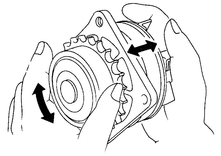
Check that the vane shaft turns smoothly by hand and is not excessively loose.
Replace the water pump assembly if the water pump does not perform properly.
INSTALLATION
Install new O-rings to water pump (1).

Hold timing chain to the side and install the water pump.
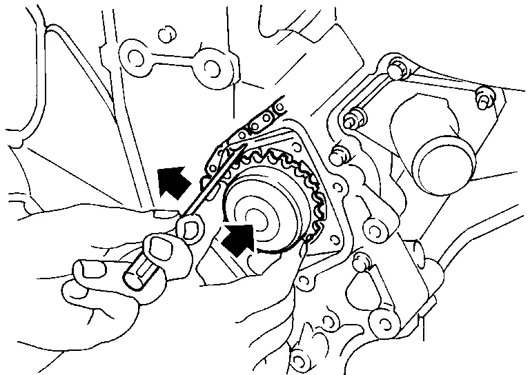
Check that timing chain and water pump sprocket are engaged.
Tighten water pump bolts alternately and evenly to specification.
Remove dust and foreign material completely from installation area of timing chain tensioner and rear timing chain case.
Turn crankshaft pulley (1) approximately 20° clockwise so that timing chain on timing chain tensioner side is loose.

Apply engine oil to the oil feed hole and timing chain tensioner and install the timing chain tensioner.
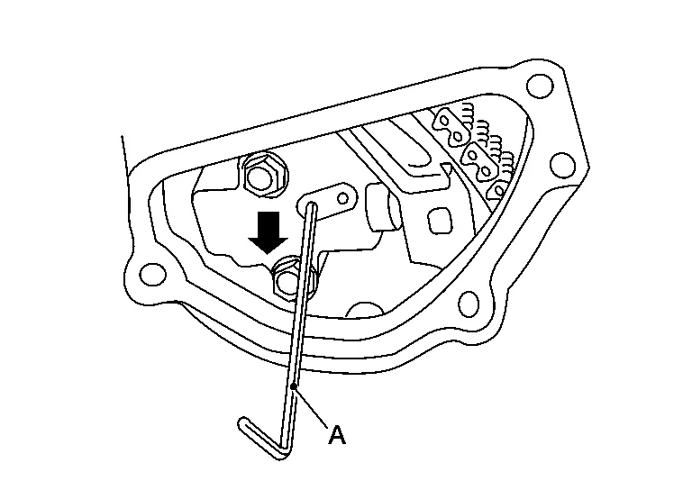
Remove the stopper pin (A).
Install valve timing control cover (bank 1) and water pump cover.Before installing, remove all traces of liquid gasket from mating surface of water pump cover and IVT cover using a scraper.
Also remove traces of liquid gasket from the mating surface of the front cover.
Apply a continuous bead of liquid gasket to mating surface of IVT cover and water pump cover. Use Genuine RTV Silicone Sealant or equivalent. Refer to Recommended Chemical Products and Sealants.Installation of remaining components is in the reverse order of removal.
After installation, refill engine coolant and check for leaks. Refer to Changing Engine Coolant and System Inspection.
Refill power steering fluid. Refer to Draining and Refilling.
After starting engine, let idle for three minutes then rev engine up to 3,000 rpm under no load to purge air from the high-pressure chamber of the chain tensioner. The engine may produce a rattling noise. This indicates that air still remains in the chamber and is not a matter of concern.
INSPECTION AFTER INSTALLATION
Before starting engine, check oil/fluid levels including engine coolant and engine oil. If less than required quantity, fill to the specified level. Refer to Fluids and Lubricants.
Use procedure below to check for fuel leaks.
Turn ignition switch ON (with engine stopped). With fuel pressure applied to fuel piping, check for fuel leaks at connection points.
Start engine. With engine speed increased, check again for fuel leaks at connection points.
Run engine to check for unusual noise and vibration.
Warm up engine thoroughly to make sure there are no leaks of fuel, exhaust gas, or any oils/fluids including engine oil and engine coolant.
Bleed air from passages in lines and hoses, such as in cooling system.
After cooling down engine, again check oil/fluid levels including engine oil and engine coolant. Refill to specified level, if necessary.
Summary of the inspection items:
Item Before starting engine Engine running After engine stopped Engine coolant Level Leakage Level Engine oil Level Leakage Level Transmission/transaxle fluid A/T and CVT Models Leakage Level/Leakage Leakage M/T Models Level/Leakage Leakage Level/Leakage Other oils and fluids* Level Leakage Level Fuel Leakage Leakage Leakage Exhaust gas — Leakage — *Power steering fluid, brake fluid, etc.