Immobiliser
Key-coded immobiliser system
GENERAL
The immobiliser is controlled by a key recognition system (known as the KEY immobiliser).
Independent coded electronics operating without a battery are built into each key head of the vehicle.
When the ignition is switched on, a ring around the ignition switch reads and picks up the code emitted by the key head and transmits it to the decoder unit.
If the decoder unit recognises the code, starting of the vehicle is then authorised.
The immobiliser is activated a few seconds after the key is removed from the ignition switch and is indicated by the red warning light on the dashboard flashing.
In the event of a fault in the key recognition system, a fallback code can be entered using the XR25 tester only.
This code will be provided to the recovery technician (on request) by the local assistance network (depending on country, e.g. Delta Assistance on 0800.05.15.15 for France). WARNING: The recovery technician must inform the customer that the immobiliser will automatically reactivate 10 minutes after the ignition is switched off.
NOTES
This system can be fitted to petrol or diesel vehicles.
Petrol vehicle: the immobiliser is handled by the injection ECU.
Diesel vehicle: the immobiliser is handled by a coded solenoid valve (on the injection pump).
If the vehicle is fitted with remote central locking, a single decoder unit performs both functions (immobiliser and remote control). The remote control has no effect on the immobiliser system (see chapter 88).
On these vehicles, the identification number of the key heads consists of eight alphanumeric characters beginning with the letter E or A.
DESCRIPTION With this system, the immobiliser is activated about 10 seconds after the ignition is switched off (indicated by the immobiliser red warning light flashing).
It consists of:
two key heads fitted with either:
coded electronics alone for controlling the immobiliser (A),
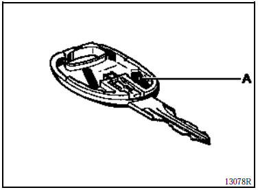
coded electronics (A) for controlling the immobiliser and remote control electronics (B) for controlling locking or unlocking of the doors (depending on equipment).
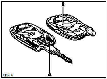
NOTE: To remove the metal insert, spread its retaining tab before removing it. On refitting, check that the insert is correctly clipped in.
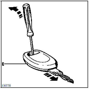
Opening a key head
Place the key head on a bench, metal insert facing down.
Lever with a small screwdriver as shown below, making sure the tip rests on the lower part (E) of the key head. This allows the upper part to slide relative to the lower part.
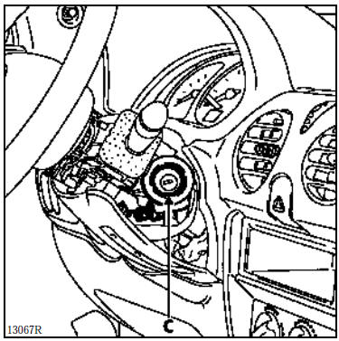
A receiver ring (C) located around the ignition switch, fitted with electronics responsible for transmitting the key code to the decoder unit (D).
NOTE: This ring is not coded.
Removal - Refitting
Remove the lower steering column shrouds, release the ignition switch ring and disconnect its connector.
A decoder unit (D) located in the dashboard on the left-hand side.
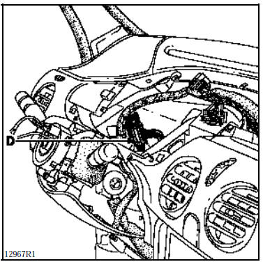
It performs the following functions:
decoding the key signal from the receiver ring,
managing the immobiliser system by sending a code to the injection ECU (petrol) or the coded solenoid valve (diesel) to authorise vehicle starting,
controlling the red immobiliser warning light,
locking or unlocking the doors (depending on version),
timed switching on of the courtesy light (vehicle fitted with remote central locking).
Removal - Refitting
To remove the decoder unit, the dashboard must be partially removed.
Remove:
the steering wheel with the wheels straight,
the lower steering column shrouds,
the knee protection panel under the steering column,
the lighting and wiper/washer control assembly,
the dashboard surround,
the dashboard,
the trim at the bottom of the driver's side dashboard,
the two speaker grilles on the dashboard,
the dashboard mountings.
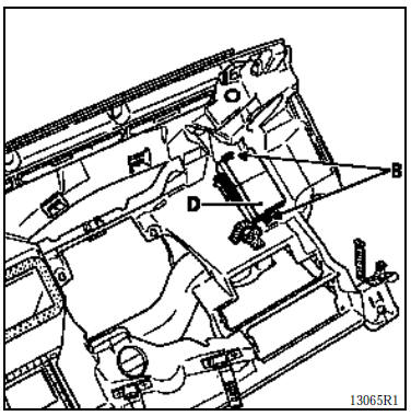
Move the dashboard as far as possible, disconnect the decoder unit and remove the two mounting screws (B) using a small ratchet fitted with a 20 star (Torx) socket.
A red immobiliser warning light on the dashboard used to:
indicate activation of the immobiliser system,
indicate a system fault on vehicles fitted with a coded solenoid valve (diesel) or key non-recognition,
indicate entry into the resynchronisation mode for the central locking remote controls (depending on equipment).
An injection warning light (petrol vehicle) which indicates a fault:
of the injection system,
of the engine-running immobiliser system (flashes during deceleration and at idle).
OPERATION
Once the immobilizer system is operational (about 10 seconds after the + after ignition is cut), the red immobilizer warning light flashes (slow flashing: one flash per second).
After switching the ignition on, the reader ring reads the key code and sends it to the decoder unit.
If the code is not recognized by the decoder unit, the injection (petrol) warning light comes on for a few seconds and goes off, while the red immobilizer warning light flashes (fast flashing).
If the code is recognized by the decoder unit, it sends a code to the injection ECU (petrol) or to the coded solenoid valve (diesel) via the coded link, and switches off the red immobilizer warning light (after about three seconds).
At this point, several cases may occur:
the injection ECU (petrol) or the coded solenoid valve (diesel) has no reference code stored in its memory:
the code sent to it is stored in its memory.
the injection ECU (petrol) or coded solenoid valve (diesel) has a reference code stored in its memory:
the code sent to it is compared with its reference code,
if the two codes match, the ECU unlocks the injection (petrol) or the coded solenoid valve (diesel) and allows the engine to start. When the ignition is switched on, the injection warning light and the immobilizer warning light come on steadily for three seconds and then go off, confirming that the system is working correctly.
if the two codes do not match, the system remains locked to prevent the engine from starting. When the ignition is switched on, the injection warning light flashes (petrol) and the red immobilizer warning light comes on and then goes off, or the red immobilizer warning light stays on continuously (diesel), indicating that the coded solenoid valve has not recognized the code. Starting the vehicle is not permitted.
NOTE: For the system to work correctly, no object (e.g. key ring) must be placed between the key and the ring.
WARNING: When the battery is weakly charged, the voltage drop caused by the starter motor load may reactivate the immobilizer. If the voltage is too low, starting is impossible, even when pushing the vehicle.
KEY HEAD REPLACEMENT
The coded electronics of the key head or remote control (depending on equipment) are faulty: - order a replacement key head using the number engraved in the faulty key head (eight alphanumeric characters beginning with the letter E or A). If the key head is fitted with a remote control, carry out a resynchronization.
WARNING: The resynchronization procedure differs depending on whether the decoder unit has been replaced or not (see specific or simple resynchronization procedure, chapter 88).
If the customer wants to be back on the road immediately (second key not available), a kit (decoder unit plus two key heads) can be fitted (see kit replacement).
The key has been lost:
order a replacement key head using the number engraved on the second key head (eight alphanumeric characters beginning with the letter E or A) or on the label (normally attached to the keys at vehicle delivery).
In this case, also order the metal insert matching the key number. If the key head is fitted with a remote control, carry out a resynchronization.
WARNING: The resynchronization procedure differs depending on whether the decoder unit has been replaced or not (see specific or simple resynchronization procedure, chapter 88).
WARNING: Do not touch the key electronics when reading the number engraved in the key head. Any key head whose electronics have been handled must be replaced without fail.
NOTE: If it is impossible to find the key head numbers (two keys lost and the label missing), the complete kit must be replaced (decoder unit plus two transmitters, plus injection ECU or coded solenoid valve electronics).
DECODER UNIT ONLY REPLACEMENT
A new decoder unit is not coded. Once fitted to the vehicle, it will therefore be necessary to teach it the code of one of the two keys so that it becomes operational (see learning procedure).
NOTE: When only the decoder unit is replaced, no action is required on the injection ECU or coded solenoid valve; they keep the same immobilizer code.
WARNING: Once a decoder unit has learned the key codes, it is impossible to erase them or to store another code in their place.
SPECIFIC FEATURES
Diesel vehicles
On these vehicles, the decoder unit is identical to the decoder unit of a petrol immobilizer system. When replacing it, the new part must be configured to "diesel" using the XR25 tool.
This configuration allows the decoder unit to monitor the correct operation of the coded solenoid valve (indicated by the immobilizer warning light) (see diesel configuration).
Vehicles fitted with remote control
After replacing the decoder unit, resynchronize the remote control (see simple resynchronization procedure, chapter 88).
LEARNING PROCEDURE
The procedure is carried out with one key only.
The XR25 tool is essential to carry out this procedure in order to lock the key learning.
With the ignition off, connect the XR25 tool to the vehicle and set the rotary selector to S8.
Enter the code

 (sheet no. 56), bargraphs 19 right and 19 left must be lit (learning not performed). If both are not lit, replace the decoder unit (this unit has already been used).
Switch the ignition on (without starting) with one of the keys (about two seconds). Bargraph 18 left lights up and bargraph 19 left goes off.
The red immobilizer warning light flashes.Switch off the ignition and run command G60* to lock the learning. The red immobilizer warning light must flash (slow flashing). Bar graphs 19 right and 18 left must be off.
Switch on the ignition for a few seconds (without starting) so the code is sent to the injection ECU or the coded solenoid valve.
Check that the immobilizer system works correctly with both keys.
Ignition off: the red immobilizer warning light must flash for 10 seconds after the ignition is switched off (slow flashing). Bar graph 10 left must be lit. The vehicle will then not start with other keys.
NOTE: To simulate a start prohibition, before switching on the ignition, wait until the red warning light changes to slow flashing.
Enter the command


 on the XR25 tool, ignition still off (bar graph 9 left lights up).
Switch on the ignition: the red immobilizer warning light flashes faster and the vehicle must not be able to start.
The procedure is complete. After switching the ignition off and back on (for more than two seconds), check that the vehicle starts with both keys.
Diesel configuration
On diesel vehicles, the decoder unit must be configured to "diesel" using the XR25 tool.
1. Ignition off, XR25 tool connected (ISO selector set to S8).
Enter the code (card no. 56). Bar graph 1 right must light up.
2. Enter the programming mode 
 Bar graph 3 right must light up.
The configuration is complete.
REPLACING A KEY SET (decoder unit plus two key heads)
When replacing a key set, the following steps are required:
teach the key code to the decoder unit (supplied uncoded),
erase the old code stored in the injection ECU or the coded solenoid valve using the troubleshooting procedure (request the old key set code number from the local support network, e.g. Delta Assistance for France).
IMPORTANT: To erase the old code (stored in the injection ECU or in the coded solenoid valve electronics), the procedure below must be followed in the exact order given.
The code in the injection ECU or coded solenoid valve can only be erased with the emergency code (using the old key set number) if the decoder unit fitted to the vehicle has learned a code, which is the case in the procedure that follows.
NOTE: If the emergency code is entered while the decoder unit has the same code as the injection ECU or coded solenoid valve, it will not decode.
Fit the metal inserts from the old keys into the new key heads.
Note the number of one of the old key heads to obtain the emergency code number.
Remove the decoder unit with the ignition off.
Fit the new decoder unit in its place (ignition off).
Connect the XR25 tool and set the ISO selector to S8.
Enter the code


Bar graphs 19 right and 19 left must be lit (learning not done).Switch on the ignition (without starting) with one of the keys (about two seconds). Bar graph 18 left lights up and 19 left goes off.
The red immobilizer warning light flashes quickly.Switch off the ignition and run command G60* to lock the learning:
the red immobilizer warning light must flash (slow flashing),
bar graphs 19 right and 18 left must be off.
Switch on the ignition for a few seconds and check that the red warning light stays on steadily (diesel) or that the injection warning light flashes (petrol).
Keep the ignition on for more than 10 consecutive seconds.
Switch off the ignition and wait for the red warning light to change to slow flashing.
Enter the command


 with the ignition still off (bar graph 9 left lights up).
Switch on the ignition: the red immobilizer warning light flashes faster.
Then follow the emergency code entry procedure (see emergency code entry procedure), using the code number for the old key set.
This erases the old code stored in the injection ECU or the coded solenoid valve.
NOTE: On petrol vehicles, the XR25 tool can be used to check that the injection ECU has been decoded (in injection diagnostics).
Connect the XR25 tester to the diagnostic socket.
Set the ISO selector and enter the injection code: bar graph 2 right (immobilizer) must be lit.
After entering 
the message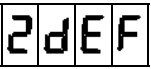
must appear on the tool display.
The erasure is then successful.
If the display shows
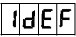
this indicates a fault on the coded line.
In this case, repair the fault and repeat the procedure.
If bar graph 2 right (immobilizer) is off and the display shows
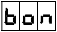 (*22),
this means the injection ECU code has not been erased. In this case, check that the emergency code number is correct and repeat the procedure.
11. Switch the ignition off and back on for a few seconds without starting, so the new key set's immobilizer code is learned by the injection ECU or the coded solenoid valve. The red warning light must come on for 3 seconds, then go off.
For diesel vehicles:
Ignition off, configure the decoder unit to "diesel" (see diesel configuration using the command

 ). Bar graph 3 right must light up, the configuration is complete.
NOTE
For petrol vehicles: using the XR25 tool, check that the injection ECU has learned the code. Bar graph 2 right (immobilizer) must be off.
After entering
the display must show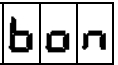
The injection ECU coding has been completed successfully.
If the display shows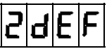 the injection ECU still has not been coded.
For diesel vehicles: when switching on the ignition, check that the immobilizer warning light goes off after 3 seconds.
12. Check that the system works correctly with both vehicle keys.
Switch the ignition on and check that the red warning light comes on for 3 seconds then goes out, and that the vehicle starts.
NOTE: It is possible to check the start prevention using the XR25 tester.
Switch off the ignition and wait for the light to flash (slow flashing).
Enter


Switch the ignition on and check that the vehicle cannot start and that the red light flashes (fast flashing).
13. The procedure is complete. After switching the ignition off and back on (for more than two seconds), check that the vehicle starts and clear all faults stored in the decoder box.
Vehicles equipped with remote control
After replacing the battery, resynchronise the remote control (see simple resynchronisation procedure, chapter 88).
REPLACING THE INJECTION ECU OR THE CODED SOLENOID VALVE
Injection ECUs and coded solenoid valves are supplied uncoded. They must therefore be taught the system code when fitted.
Simply carry out the following operations:
switch the ignition on without starting, using the vehicle's coded key, for a few seconds,
switch off the ignition. The immobiliser function will be active approximately 10 seconds later (the red immobiliser light flashes).
NOTE: It is possible to check the start prevention using the XR25 tester:
Ignition off, wait for the red light to switch to slow flashing.
Enter the command with the ignition still off (bar graph 9 left lights up).
Switch on the ignition: the red immobilizer warning light flashes faster and the vehicle must not be able to start.
NOTE: For removal and refitting, refer to the corresponding chapter (13 or 17).
SPECIAL TESTING CONDITIONS FOR AN INJECTION ECU OR A CODED SOLENOID VALVE (test part)
WARNING: When testing an injection ECU or uncoded solenoid valve electronics borrowed from the store (test part), the decoder box MUST NOT be powered during the work.
When the decoder box is powered, switching the ignition on sends the coded frame from the decoder box to the injection ECU or to the solenoid valve electronics (the code is then learnt).
To avoid storing a code that could make the injection ECU or coded solenoid valve electronics unusable after the test, remove the (+AVC) fuse from the decoder box (fuse marked with the central locking symbol). This way the coded frame will not be sent when the ignition is switched on, and the ECU or solenoid valve electronics will remain uncoded.
On petrol vehicles, the ECU used for the test MUST have the same part number as the vehicle's original ECU (risk of destroying the test ECU).
Check (petrol vehicles only)
If the test ECU must be returned to the store, it is possible (before removing it) to check with the XR25 tester that it has not coded itself during the test (e.g. due to incorrect handling).
Connect the XR25 tester to the diagnostic socket.
Set the ISO selector and enter the injection code: bar graph 2 right (immobilizer) must be lit.
After entering

the message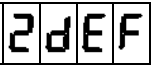 must appear on the tool display.
This indicates that the injection ECU is not coded; it can be returned to the store.
If right-hand bar graph 2 (immobiliser) is off and after entering
the message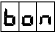 appears on the tester display, this indicates that the ECU has learnt the immobiliser system code (incorrect handling). In this case, the ECU must be decoded before being returned to the store.
The decoding procedure consists of replacing the vehicle's decoder box with another decoder box with a different code (with its key head) and entering the vehicle's recovery code (to be requested from the local assistance network, e.g. Delta Assistance for France), using the number printed on the vehicle's key head.
Ignition off, fit in place of the vehicle's original decoder box a decoder box coded with a different number (the procedure will not work with an uncoded decoder box or one coded with the same number as the injection ECU).
Switch the ignition on. The red immobiliser light flashes (fast flashing).
Enter the vehicle's recovery code (number corresponding to the original key number).
After entering the recovery code, the red light flashes again.
On the XR25 tester, the display should read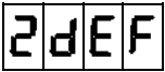 (in injection diagnostics). This indicates that the injection ECU has been decoded.
Switch off the ignition, remove the decoded ECU and return it to the store.
Refit the ECU and the decoder box in the vehicle.
NOTE: When carrying out an injection check with the XR25 tester on a vehicle without immobiliser, it is normal for right-hand bar graph 2 to be lit (*22 = 2 def = ECU not coded).
SYSTEM FAULT WITH ENGINE RUNNING
Petrol vehicle
If a system fault is detected by the engine management ECU while the engine is running, the injection warning light on the dashboard will flash during deceleration and at idle (speed below 1500 rpm).
WARNING: In this case, after repair, the fault stored in the injection ECU and in the decoder box must be cleared by entering command mode 


 using the XR25 tester, or by disconnecting the battery (approximately 30 seconds), so that the immobiliser system can be reactivated.
NOTE: This fault can be displayed by the XR25 tester (via injection diagnostics).
Connect the XR25 tester and enter the injection code.
The fault can be displayed by right-hand bar graph 2.
After entering 
the message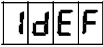 on the tester display indicates a fault on the coded line.
Diesel vehicle: If a system fault is detected by the decoder box while the engine is running, the red immobiliser light will remain steadily lit until the ignition is switched off.
WARNING: In this case, after repair, the fault stored in the decoder unit must be erased by entering command mode using the XR25 tool, so that the immobiliser system can be reactivated.
NOTE: This fault can be read with the XR25 tool through the decoder unit diagnosis (sheet no. 56).
Connect the XR25 tool.
Set the rotary selector to S8.
Enter the code


The fault can be read on the left or right bar graph 6.
FAULT CODE ENTRY PROCEDURE
With this immobiliser system, the fault code entry procedure is managed by the decoder unit.
The code can only be entered using the XR25 tool.
The fault code can only be entered if the immobiliser system is active. The red warning light must flash when the ignition is switched on (fast flashing).
After obtaining the fault code number (from the local service network, e.g. Delta Assistance for France), carry out the following operations:
Ignition off, the immobiliser red warning light must flash (slow flashing).
Switch the ignition on. The injection indicator (petrol vehicles) lights for about 3 seconds then goes out, while the immobiliser red warning light must flash faster.
Connect the XR25 tool to the vehicle and set the rotary selector to S8.
Enter the code Bar graph 10 left must be lit (diagnostic sheet no. 56).
4. Enter the mode


 on the XR25 tool keypad, then enter the fault code number and confirm with the
If the code is correct
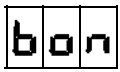 is displayed on the tool.
Bar graph 10 left goes out.
The engine can be started.
The vehicle will be protected again either:
about 10 minutes after the ignition is switched off (automatic restart),
after disconnecting the battery.
If the code is incorrect
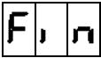 is displayed on the tool.
Bar graph 10 left stays lit.
The engine still cannot be started.
The immobiliser red warning light and the injection indicator (depending on version) flash.
Switch the ignition off, then repeat the code entry procedure.
WARNING: You have 3 attempts to enter the code. If the code is still invalid after the 3rd attempt, wait about 15 minutes before trying again.
Once this delay has elapsed, switch the ignition off and back on; three attempts are allowed again.
NOTE: This procedure does not decode the injection ECU or the coded solenoid valve (depending on engine), it only allows the vehicle to be started.
REMINDER: Between two code entry attempts, the ignition must be switched off and back on.
DECODER UNIT WIRING DIAGRAM (most complete)
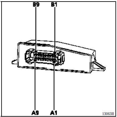
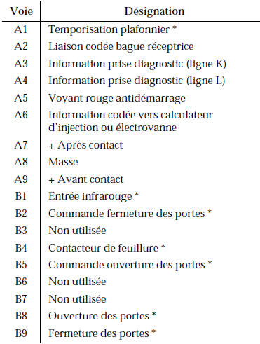
* Vehicle equipped with remote control
CIRCUIT DIAGRAM (vehicle equipped with remote control)
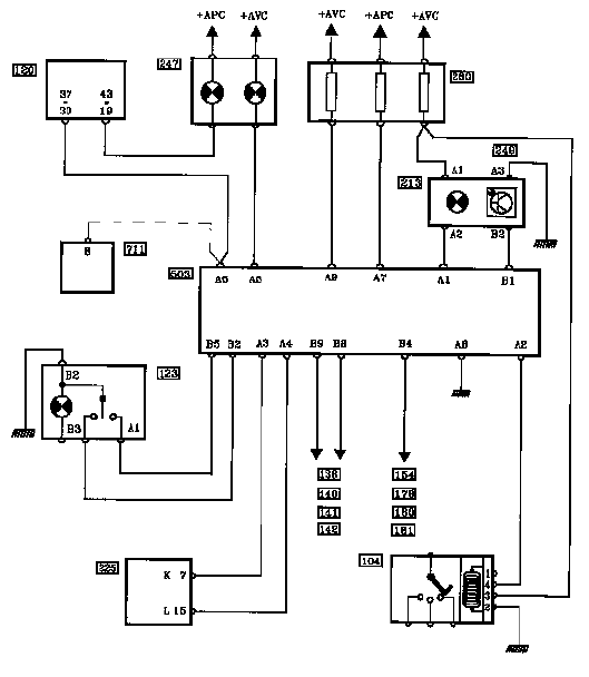
KEY TO COMPONENTS
104 Starter switch
120 Injection ECU
123 Central locking button
138 Rear right door central locking motor
140 Driver's door central locking motor
141 Passenger door central locking motor
142 Tailgate central locking motor
154 Tailgate switch
178 Rear right door jamb switch
180 Driver's door jamb switch
181 Passenger door jamb switch
213 Interior light
225 Diagnostic socket
247 Injection indicator and immobiliser red warning light in instrument panel
249 Remote control receiver
260 Passenger compartment fuse box
503 Decoder unit
711 Coded solenoid valve
DIAGNOSIS
If this immobiliser system fails, a diagnosis can be carried out using the XR25 tool.
WIRING
Use cartridge no. 17 and the corresponding diagnostic sheet no. 56.
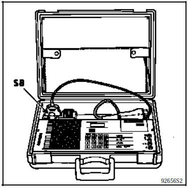
Connect the XR25 tool to the diagnostic socket.
Set the rotary selector to S8.
Enter the code specific to the immobiliser system D56.
NOTE: For interpreting the bar graphs, fault location trees, conformity checks and additional checks, see the diagnosis chapter.
Test yourself
A quick Renault Kangoo quiz: every answer comes with an explanation and a link to the manual page.