Interpreting XR25 bar graphs

INSTRUCTIONS For diagnosis, this bargraph must be lit.
| Try the diagnostic tool on another vehicle. |
Check:
Repair if necessary. |
Check:
Repair if necessary. |
Check, ignition on, for 12 V on pin:
Repair if necessary. |
Connect the breakout box in place of the ECU and check the insulation and continuity of the circuit: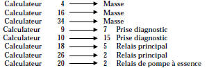 Repair if necessary. |
Check, ignition on, for 12 V on pin 5 of the main relay:
|
AFTER REPAIR Clear the ECU memory using G0**.
Try to start the vehicle. Switch the ignition on, then deal with the other faults.
Do not forget to carry out a status and parameters check!

INSTRUCTIONS Nothing to report.
The ECU must be non-compliant or faulty. Replace the ECU.
AFTER REPAIR Clear the ECU memory using G0**.
Try to start the vehicle. Switch the ignition on, then deal with the other faults.
Do not forget to carry out a status and parameters check!

NOTE Ignore this bar graph if the vehicle does not have an immobilizer.
| Connect the breakout box in place of the ECU and check insulation, continuity and the absence of parasitic resistance on the pin 30 wiring of the ECU. Repair if necessary. |
| The fault persists, refer to the immobilizer diagnosis. |
AFTER REPAIR Clear the ECU memory using G0**.
Try to start the vehicle. Switch the ignition on, then deal with the other faults.
Do not forget to carry out a status and parameters check!

NOTE In certain fault cases, the BG 6D may flash. If BG 4G, BG 5G, BG 6G or BG 6D are also on, check line 15 of the ECU.
Connect the breakout box in place of the ECU and check the insulation and continuity of the circuit: Repair if necessary. |
| Check the sensor resistance. Replace it if necessary. |
| The problem is still not resolved! The injection ECU must therefore be replaced. WARNING: The destruction of the ECU is probably due to an electrical shock. The cause of the destruction must be found before fitting a new ECU. |
AFTER REPAIR Clear the ECU memory using G0**.
Try to start the vehicle. Switch the ignition on, then deal with the other faults.
Do not forget to carry out a status and parameters check!

NOTE If BG 3D is flashing, raise engine speed to 2500 rpm for 5 minutes.
If BG 3D has become steady, diagnose the fault.
| Check the connection and the condition of the oxygen sensor connector. |
Check, with the ignition on during the delay phase, for the presence of:
Repair if necessary. |
| Check for earth on pin 4 of the injection ECU. Repair if necessary. |
Connect the breakout box in place of the ECU and check the insulation and continuity of the circuit: Repair if necessary. |
| The fault persists. Replace the oxygen sensor. |
| The problem is still not resolved! The injection ECU must therefore be replaced. WARNING: The destruction of the ECU is probably due to an electrical shock. The cause of the destruction must be found before fitting a new ECU. |
AFTER REPAIR Run the engine, switch ignition on and erase the ECU memory using G0**. Try to start the vehicle. Switch ignition on, then troubleshoot the other faults. Don't forget to check the states and parameters!

NOTE If BG 3G, BG 5G, BG 6G or BG 6D is also on, check line 15 of the ECU.
In certain fault cases, BG 4G can only be on steady with the engine running.
Connect the breakout box in place of the ECU and check the insulation and continuity of the circuit: Repair if necessary. |
| Check the sensor resistance. Replace if necessary. |
| The problem is still not resolved! The injection ECU must therefore be replaced. WARNING: The ECU has probably been destroyed by an electrical shock. Find the cause of the failure before fitting a new ECU. |
AFTER REPAIR Clear the ECU memory using G0**.
Try to start the vehicle. Switch the ignition on, then deal with the other faults.
Do not forget to carry out a status and parameters check!

INSTRUCTIONS Carry out a road test if bargraph 4D is flashing.
| Check that the sensor is correctly positioned. |
Check, on the vehicle speed sensor, for the presence of:
Repair if necessary. |
Connect the breakout box in place of the ECU and check the insulation, the continuity and the absence of parasitic resistance on the line: Repair if necessary. |
| The fault persists! Replace the sensor. |
| The problem is still not resolved! The injection ECU must therefore be replaced. WARNING: The destruction of the ECU is probably due to an electrical shock. The cause of the destruction must be found before fitting a new ECU. |
AFTER REPAIR Clear the ECU memory using G0**.
Try to start the vehicle. Switch the ignition on, then deal with the other faults.
Do not forget to carry out a status and parameters check!

NOTE If BG 6D is also on, check line 5 of the ECU. If BG 4G, BG 3G, BG 6G or BG 6D is also on, check line 15 of the ECU.
| Check that the pressure sensor is connected electrically and pneumatically. Check the condition of the pressure sensor hose (it must not be blocked, punctured, etc.). |
Connect the breakout box in place of the ECU and check the insulation, the continuity and the absence of parasitic resistance on the line: Repair if necessary. |
| The fault persists! Replace the sensor. |
| The problem is still not resolved! The injection ECU must therefore be replaced. WARNING: The destruction of the ECU is probably due to an electrical shock. The cause of the destruction must be found before fitting a new ECU. |
AFTER REPAIR Clear the ECU memory using G0**.
Try to start the vehicle. Switch the ignition on, then deal with the other faults.
Do not forget to carry out a status and parameters check!

NOTE Attempt to start BG 5D with the starter motor.
BG 5D is often seen flashing, *25 = dEF, because its ignition...
| *25 = CO.0 *25 = CC.0 |
Check the target sensor resistance. Replace the sensor if necessary. |
| Check the condition of the flywheel, especially if it has been removed. | |
Connect the breakout box in place of the ECU and check the insulation, the continuity and the absence of parasitic resistance on the line: Repair if necessary. |
|
| The problem is still not resolved! The injection ECU must therefore be replaced. WARNING: The ECU has probably been destroyed by an electrical shock. Find the cause of the failure before fitting a new ECU. |
|
| *25 = In | Check that the target sensor is connected correctly (the sensor connector must not be reversed). Repair if necessary. |
| The fault persists! Replace the sensor. |

NOTE In certain fault cases, BG 6G can only be on steady at 3000 rpm.
for 1 minute. If BG 4G, BG 5G, BG 3G or BG 6D is also on, check line 15 of the ECU.
Connect the breakout box in place of the ECU and check the insulation, the continuity and the absence of parasitic resistance on the line: Repair if necessary. |
| The fault persists! Replace the knock sensor. |
| The problem is still not resolved! The injection ECU must therefore be replaced. WARNING: The destruction of the ECU is probably due to an electrical shock. The cause of the destruction must be found before fitting a new ECU. |
AFTER REPAIR Clear the ECU memory using G0**.
Try to start the vehicle. Switch the ignition on, then deal with the other faults.
Do not forget to carry out a status and parameters check!

NOTE If BG 6D is flashing and BG 3G is steady, diagnose BG 3G. If BG 5G is also on steady, check line 5 of the ECU. If BG 4G, BG 5G, BG 6G or BG 3G is also on, check line 15 of the ECU.
| Check the resistance of the throttle potentiometer. Replace the throttle potentiometer if necessary. |
Connect the breakout box in place of the ECU and check the insulation, the continuity and the absence of parasitic resistance on the line: Repair if necessary. |
| The problem is still not resolved! The injection ECU must therefore be replaced. WARNING: The destruction of the ECU is probably due to an electrical shock. The cause of the destruction must be found before fitting a new ECU. |
AFTER REPAIR Clear the ECU memory using G0**.
Try to start the vehicle. Switch the ignition on, then deal with the other faults.
Do not forget to carry out a status and parameters check!

NOTE An open circuit (CO) or a short to earth (CC-) on line 20 of the ECU prevents communication with the ECU.
Check the line for insulation from 12 V: Repair if necessary. |
| The fault persists! Replace the fuel pump relay. |
| The problem is still not resolved! The injection ECU must therefore be replaced. WARNING: The destruction of the ECU is probably due to an electrical shock. The cause of the destruction must be found before fitting a new ECU. |
AFTER REPAIR Clear the ECU memory using G0**.
Try to start the vehicle. Switch the ignition on, then deal with the other faults.
Do not forget to carry out a status and parameters check!

NOTE XX = 14 => Cylinder 1 or 4, ECU line 33
XX = 23 => Cylinder 2 or 3, ECU line 32
| Check the resistance of the two injectors concerned. Replace the injector(s) if necessary. |
| With ignition on and during the time-delay phase, check for 12 V on pin 1 of the faulty injector. Repair if necessary the wiring between injector 1 and fuel pump relay pin 5. |
Connect the breakout box in place of the ECU and check the insulation and continuity of the line: Repair if necessary. |
The problem is still not resolved! The injection ECU must therefore be replaced.CAUTION: The ECU failure is probably due to an electrical shock.The cause of the failure must be found before fitting a new ECU. |
AFTER REPAIR Clear the ECU memory using G0**.
Try to start the vehicle. Switch the ignition on, then deal with the other faults.
Do not forget to carry out a status and parameters check!

NOTES Nothing to report
Ignore this bar graph with this ECU.
AFTER REPAIR Clear the ECU memory using G0**.
Try to start the vehicle. Switch the ignition on, then deal with the other faults.
Do not forget to check the status and parameters.

INSTRUCTIONS Nothing to report.
| Check the condition of the warning light and its power supply. Repair if necessary. |
Connect the breakout box in place of the ECU and check the insulation and continuity of the circuit: Repair. |
AFTER REPAIR Clear the ECU memory using G0**.
Try to start the vehicle. Switch the ignition on, then deal with the other faults.
Do not forget to carry out a status and parameters check!

INSTRUCTIONS Nothing to report.
This bargraph only lights up if the ECU power supply has been cut (disconnecting the battery, the ECU, etc.).Check the ECU power supply:
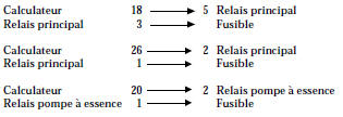
Repair if necessary.
Run the engine.
Switch off the ignition and wait for communication between the tester and the ECU to be lost.
Switch on the ignition.
Establish communication with the ECU.
Erase the ECU memory using G0**.
NOTE: Stored faults are erased. It is therefore useful to carry out a road test to check that there are no faults in the injection system.
AFTER REPAIR Clear the ECU memory using G0**.
Try to start the vehicle. Switch the ignition on, then deal with the other faults.
Do not forget to carry out a status and parameters check!

INSTRUCTIONS Nothing to report.
| Check the resistance of the idle speed control stepper motor. Check the idle control valve if necessary. |
Check the insulation, continuity and absence of parasitic resistance of the line: Repair if necessary. |
| The problem is still not resolved! The injection ECU must therefore be replaced. WARNING: The destruction of the ECU is probably due to an electrical shock. The cause of the destruction must be found before fitting a new ECU. |
AFTER REPAIR Clear the ECU memory using G0**.
Try to start the vehicle. Switch the ignition on, then deal with the other faults.
Do not forget to carry out a status and parameters check!

NOTE Nothing to report
| Check the resistance of the EVAP purge valve. Replace the valve if necessary. |
| Check, ignition on, for 12 V on pin A of the canister purge valve. Repair if necessary. |
Connect the breakout box in place of the ECU and check the insulation and continuity of the circuit: Repair if necessary. |
| The problem is still not resolved! The injection ECU must therefore be replaced. WARNING: The destruction of the ECU is probably due to an electrical shock. The cause of the destruction must be found before fitting a new ECU. |
AFTER REPAIR Run the engine, switch ignition on and erase the ECU memory using G0**. Try to start the vehicle. Switch ignition on, then troubleshoot the other faults. Don't forget to check the states and parameters!

INSTRUCTIONS Nothing to report.
Ignore this bar graph with this ECU.
AFTER REPAIR Clear the ECU memory using G0**.
Try to start the vehicle. Switch the ignition on, then deal with the other faults.
Do not forget to carry out a status and parameters check!

NOTE XX = 14 => Cylinder 1 or 4, ECU line 35
XX = 23 => Cylinder 2 or 3, ECU line 17
| Check the condition of the suppression capacitor on pin 4 of the coil. |
| Check the coil resistance. Replace the coil if necessary. |
| Check the +APC supply to the relevant coil on pin 3. Repair if necessary. |
Connect the breakout box in place of the ECU and check the insulation and continuity of the line: Repair if necessary. |
| The problem is still not resolved! The injection ECU must therefore be replaced. WARNING: The destruction of the ECU is probably due to an electrical shock. The cause of the destruction must be found before fitting a new ECU. |
AFTER REPAIR Run the engine, switch ignition on and erase the ECU memory using G0**. Try to start the vehicle. Switch ignition on, then troubleshoot the other faults. Don't forget to check the states and parameters!
Test yourself
A quick Renault Kangoo quiz: every answer comes with an explanation and a link to the manual page.