Electronically controlled systems
BOSCH wheel anti-lock braking system
This vehicle is fitted with a BOSCH 5.3 additional-type ABS with four channels; the conventional braking system and the ABS system are separate.
FEATURES
The system has four speed sensors. Each hydraulic brake channel is associated with a sensor located at each wheel. Thus, the front wheels are controlled separately. However, the rear wheels are controlled simultaneously in the same way, according to the select-low principle (the first wheel that tends to lock immediately triggers control across the whole axle). The proportioning valve performs its usual function
LOCATION OF BOSCH ABS COMPONENTS
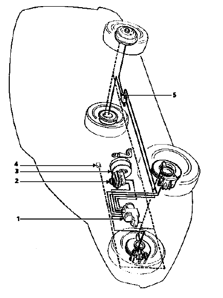
- Hydraulic unit
- Master cylinder
- Brake booster
- Brake fluid level warning light
- Brake compensator
OVERVIEW OF THE HYDRAULIC CONTROL UNIT
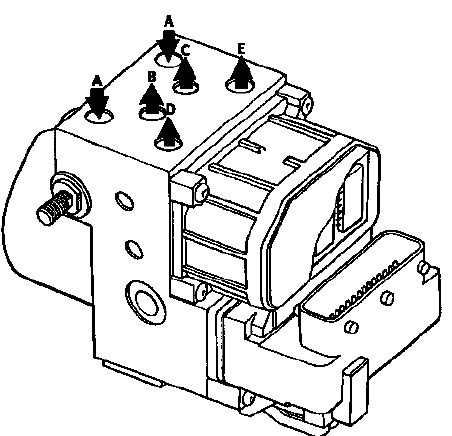
- Master cylinder inlet
- Left rear wheel
- Right rear wheel
- Right front wheel
- Left front wheel
WIRING DIAGRAM
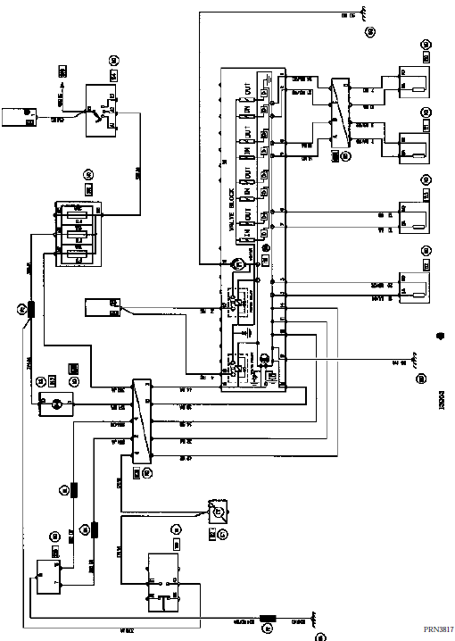
WIRING DIAGRAM KEY
104 Anti-start switch
118 ABS control unit
150 Right rear wheel sensor
151 Left rear wheel sensor
152 Right front wheel sensor
153 Left front wheel sensor
160 Brake light switch
225 Diagnostic socket
247 Instrument panel
260 Fuse box
777 Power supply fuse panel
R2 Dashboard/Rear left
R36 ABS / Dashboard
R101 Right side member/Right headlamp
31-WAY CONNECTOR
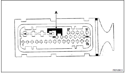
A Micro-spring connecting pins 20 and 21 (ABS and NIVOCODE warning lamps) to earth (terminal 19) if the connector is disconnected.
Connector pin assignment
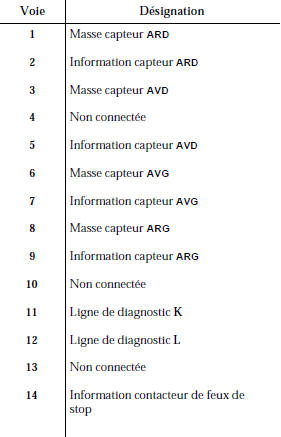
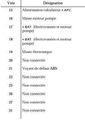
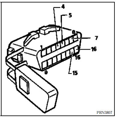
4 Chassis earth
5 Electronic earth
7 K-line diagnostic
15 L-line diagnostic
16 + battery
HYDRAULIC UNIT
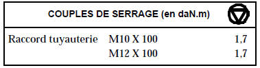
REMOVAL
Place the vehicle on a two-post lift.
Disconnect the battery.
Remove the front right wheel.
Fit a pedal depressor to limit the flow of brake fluid.
From above: disconnect the control unit connector.
Remove the two earth screws.
Disconnect the six pipes from the hydraulic unit, marking their positions for refitting.
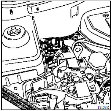
Remove the upper fixing screw (1) of the hydraulic unit.
From below:
Remove:
- the exhaust downpipe,
- the exhaust manifold heat shield (3 screws),
- the two lower fixing screws of the hydraulic unit,
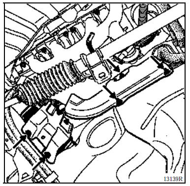
- the hydraulic unit through the wheel arch.
INSTALLATION
Refit in reverse order of removal.
NOTE: the control unit must not be removed. In case of fault, replace the complete hydraulic unit.
BRAKE HYDRAULIC CHECK
This section describes the test performed with the XR25 tester to check the fitting of the ABS in the vehicle and, more particularly, the hydraulic circuit.
NOTE: this test requires two people. The vehicle should preferably be placed on a two-post lift.
Test principle
Vehicle on lift, with the wheel to be tested raised. One operator must be in the cabin at the driver's position with the XR25 tester. Switch on the ignition, vehicle in neutral, in diagnostic mode, and press the brake pedal. The second operator must apply torque to the wheel to try to turn it.
The operator sends an appropriate command to the XR25 tester, which performs ten cycles of alternating pressure drop and pressure rise on the wheel being checked. These actions on the ABS result in the wheel being alternately released and locked ten times. The jerky movements of the wheel, recorded qualitatively by the operator, confirm that the hydraulic circuit of this wheel is correctly connected.
The program in the XR25 tester for this sequence is as follows:
- Cycle on the wheel to be tested:
- a pressure drop lasting 200 ms with the pump starting simultaneously,
- a pressure rise lasting 300 ms with the pump starting simultaneously (ten cycles are performed on the wheel concerned).
- A pressure rise to master cylinder pressure on all four wheels.
- The hydraulic pump motor stops.
- The operator releases the brake pedal.
The hydraulic test of the wheel concerned is complete. Repeat the check for the other three wheels.
BLEEDING PROCEDURE
NOTE: the hydraulic unit is pre-filled.
This bleeding procedure applies after removing any of the following components:
- the hydraulic unit,
- the master cylinder,
- the piping (between hydraulic unit and master cylinder).
1) Perform the conventional brake circuit bleeding with the brake pedal.
NOTE: if, after a road test with ABS regulation, the pedal travel is not correct, bleed the hydraulic unit.
2) Bleed the hydraulic unit.
IMPORTANT: follow the bleeding sequence, starting with the rear right brake, then rear left, front left, and finally front right.
a) Bleed the rear right brake by performing the secondary circuit bleed on the hydraulic unit using the XR25 kit:
- position the bleed container and hose, open the brake bleed screw,
- press the brake pedal repeatedly (about ten strokes),
- start the bleed command on the XR25 kit,
- pump the brake pedal during the diagnostic bleed phase,
- at the end of the XR25 bleed cycle, continue pumping the brake pedal and close the brake bleed screw.
b) Carry out the procedure described in a) for the rear left, front left and front right brakes.
c) Check the pedal travel. If it is not satisfactory, repeat the bleeding procedure.
IMPORTANT: make sure there is sufficient brake fluid in the reservoir.
WHEEL SPEED SENSOR CHECK
- Perform a resistance check of the sensor wiring (from the control module connector to the two-way wheel speed sensor connector).
- Visually check the tone wheel teeth (26 teeth). If they are defective, replace the tone wheel.
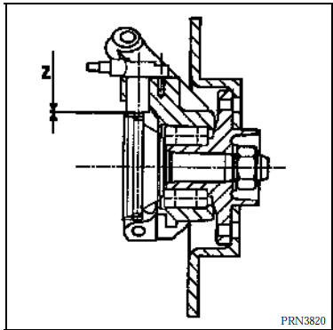
- Check the air gap using a set of feeler gauges. Only the front can be checked.
PRN3820
Front: 0.13 < Z < 1.96 mm
Test yourself
A quick Renault Kangoo quiz: every answer comes with an explanation and a link to the manual page.