Fault location tree
| ALP 1 | No communication with the ECU |
INSTRUCTIONS
Carry out a multiplexed network test.
| Check the battery voltage. Check the condition and connection of the terminals and of the battery fuse box fuses. Repair if necessary. |
| Check for + 12 V on the power screw terminal of the Protection and Switching Unit. If not compliant, check the wiring and connection between the battery and the Protection and Switching Unit. |
| Check for earth (ground) on pin 3 of connectors PPH1 and PPH2. If necessary, repair the faulty wiring and/or connector. |
| Check for 12 V on connector P2. If necessary, repair the faulty wiring and/or connector. |
| Check the condition and connection of connector PEH. Repair if necessary. |
| If everything is correct, contact your Techline. |
AFTER REPAIR
Carry out a conformity check and deal with any other malfunctions found.
| ALP 2 | The starter motor does not operate |
INSTRUCTIONS
Check for the absence of faults on the multiplexed network by running the network test.
Check that the starting conditions are met by referring to the "Starting" function.
Check that state ET010: Starting conditions met is "YES" following a press of the start button; otherwise, refer to the troubleshooting for this state.
Check the condition and connection of fuse 3 on the UPC.
| Check the condition and connection of connector PPM1 on the UPC and of the control terminal on the starter motor. Repair if necessary. |
| If all is correct, check for 12 V on the starter motor control terminal with the starter motor activated. If compliant, diagnose the starter motor. |
| Check the insulation and continuity of the wiring between UPC connector PPM1 pin 3 and the starter motor control terminal. Repair if necessary. |
| If the problem is not resolved, contact your techline. |
AFTER REPAIR
Carry out a conformity check and deal with any other malfunctions found.
| ALP 3 | The UPC does not carry out a request from another control unit |
INSTRUCTIONS
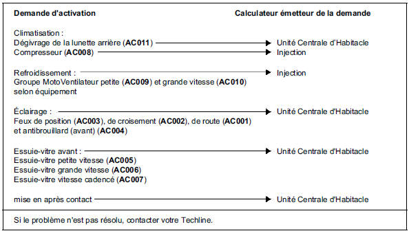
Confirm the absence of faults on the multiplexed network by running the network test.
Check that the control unit hosting the function confirms the request by reading the states.
If the request is active, check the operation of the UPC by activating the commands and using the associated diagnostic method.
AFTER REPAIR
Carry out a conformity check and deal with any other malfunctions found.
| ALP 4 | No backlighting for the various functions in the passenger compartment |
INSTRUCTIONS
The position lights must not be faulty; otherwise, refer to the troubleshooting for command "AC003 Position lights".
| Check the condition and connection of the faulty function(s). Repair if necessary. |
| Check for earth (ground) on the faulty function(s). Repair if necessary. |
| With the position lights on, check for 12 V on the faulty function(s). If compliant, replace the faulty component. |
| Check the insulation and continuity between the faulty function and the Protection and Switching Unit: Climate control panel, radio, multifunction display, mirror controls, front and rear window lift controls and window lock, door central locking switch, dashboard dimmer control and headlamp levelling control.→ Way 6 of PPH2 connector of Protection and Switching Unit Repair if necessary. |
AFTER REPAIR
Carry out a conformity check and deal with any other malfunctions found.
| ALP 5 | No accessory switching – power supply fault |
INSTRUCTIONS
Check the battery voltage.
Check that there are no faults.
Check that the accessory activation request is active in the Cabin Central Unit.
| Check the condition and connection of fuses 5L, 5D, 5E, 5F, 5G and 5H. Repair if necessary. |
| Check the condition and connection of connectors PEH, PPH1, PPH2 and PPM2 on the Protection and Switching Unit. Repair if necessary. |
| Check for 12 V on the power terminal of the Protection and Switching Unit. If necessary, repair the connection between the battery and the Protection and Switching Unit. |
| Check for 12 V on the ways corresponding to the supplies for each ECU or function. Ignition off: Anti-lock braking system ECU → PPH1 connector way 1 NOTE: If 12 V is still present on way 8 of the PPH2 connector with ignition on, contact your Techline. Ignition on:Injection ECU → PEH connector way 1 If not compliant, contact your Techline. |
AFTER REPAIR
Carry out a conformity check and deal with any other malfunctions found.
Test yourself
A quick Renault Megane quiz: every answer comes with an explanation and a link to the manual page.