Fault location tree
| ALP 1 | No communication with the ECUs |
INSTRUCTIONS
Power supply to the vehicle ECUs for diagnosis: vehicle badge on the badge holder.
Press and hold the "start" button (for more than 5 seconds) when the start conditions are not met (for example: a gear is engaged).
Connect the diagnostic tool and carry out the required operations.
WARNING: To power the Xenon lamp ECUs, switch on the dipped beam.
| Try the diagnostic tool on another vehicle. Check that the tool has an update later than CD-ROM No. 29. |
Check:
|
| Check that the CLIP probe is powered by pins 16 (+ 12 V) and 4 and 5 (earth) of the diagnostic socket, shown by the two red LEDs on the probe lighting up. Check that the CLIP probe is powered by the computer's USB port. Check that the CLIP probe communicates with the vehicle ECUs, shown by the two green LEDs on the probe lighting up.green LEDs red LEDs  |
| Check the following circuits at the diagnostic socket: pin 1 → + After ignition Repair if necessary. |
No communication on the CAN network
| Check the continuity and insulation of the lines: CAN H (pin 6 of the diagnostic socket) |
| Using a multimeter, check that the voltages at the diagnostic socket terminals are: - 2.5 V between CAN H (pin 6) and earth (pins 4 and 5) |
| To detect a short circuit on the vehicle's multiplex network, refer to the section "Aid to locating a short circuit on the network" in this chapter. |
No communication via the K-line
Check the continuity, insulation and absence of parasitic resistance on the K-line of the diagnostic socket (pin 7).| ALP 2 | No topology diagram displayed during the multiplex network test |
INSTRUCTIONS
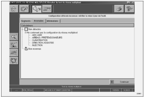
Topology display is not possible in the following cases:- The two ECUs holding the multiplex network configuration did not respond.
- The multiplex network is faulty, so communication is impossible.
- In the "multiplex network" tab of the configuration screen, an incorrect "network version" number has been entered in one of the two ECUs holding the network configuration.
- No "network version" has been entered in either of the two ECUs holding the configuration.
| ALP 3 | Configuration table display |
INSTRUCTIONS
ALP to be carried out if the tool loads the configuration screen at the end of the multiplex network test.
The configuration table remains accessible at all times via the "configuration" icon.
The RENAULT diagnostic tool loads the configuration screen directly in the following cases:- "MULTIPLEX NETWORK" tab
- Inconsistency between the "network version" numbers entered in the two ECUs holding the multiplex network configuration.
- Inconsistency in the list of ECUs entered in the ECUs holding the multiplex network configuration.
- The "network version" number on at least one of the two ECUs holding the multiplex network configuration is incorrect.
- One of the two ECUs holding the network version is blank (case of an airbag ECU or Passenger Compartment Central Unit replacement).
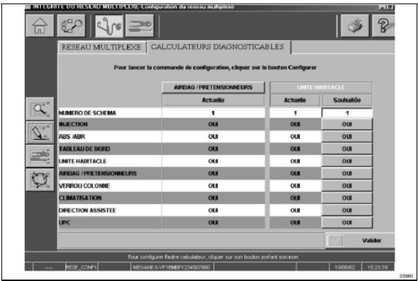
- "DIAGNOSABLE ECUS" tab (see screen below)
- Inconsistency between the "diagram number" values entered in the two ECUs holding the configuration.
- Inconsistency in the list of diagnosable control units recorded in the two control units that carry the list of diagnosable control units.
- Inconsistency between the list of recorded control units and the control units actually detected on the vehicle.
Test yourself
A quick Renault Megane quiz: every answer comes with an explanation and a link to the manual page.